Lab 8 - IBM MQ Appliance Disaster Recovery (DR)
VMs required:
- Windows 10 x64
- MQAppl1
- MQAppl2
- MQAppl3
The lab environment consists of three virtual appliances, MQAppl1, MQAppl2, and MQAppl3, and the Windows image, Windows 10 x64, to perform console operations and testing. There are other virtual appliances (MQAppl4, MQAppl5, MQAppl6, and MQAppl7) that will not be used in this lab. You should suspend them.
Introduction
The MQ Appliance Disaster Recovery (DR) feature supports flexible DR topologies consisting of ‘live’ appliances at multiple sites. DR support is provided at the Queue Manager (QM) level, so they can be configured independently according to DR policy – e.g. using a simple main/recovery site DR strategy or multi-site main/recovery strategy.
Just one network connection is required for DR between the MQ Appliances hosting the Queue Managers. The appliances are designed to tolerate a level of network latency between distant sites – different than High Availability on the MQ appliances, which tend to be in close proximity, and are designed for automatic takeover with no data loss.
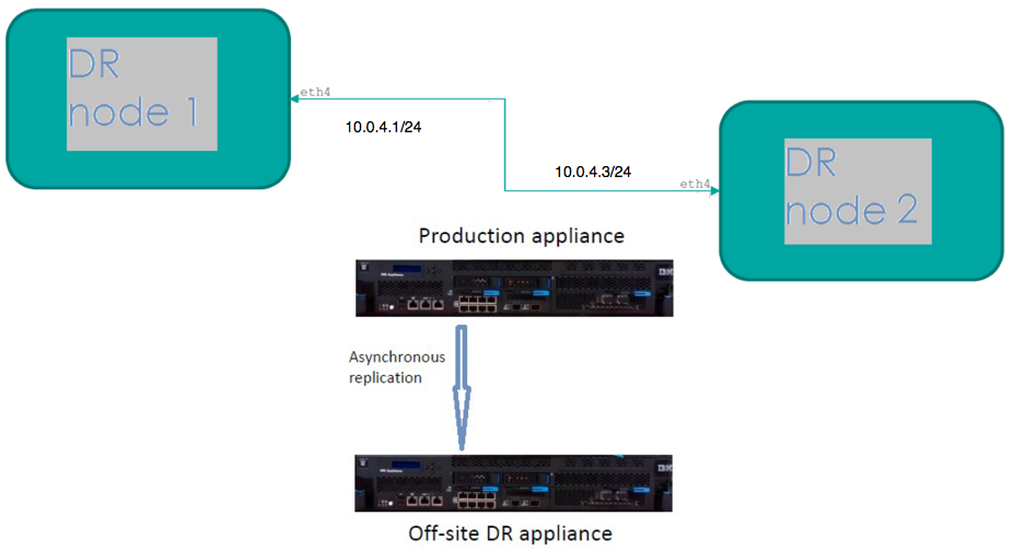
In a simple scenario, if a ‘main’ site fails, the recovery process begins to ensure business continuity. One or several of the Queue Managers on the ‘main’ appliance are to be recovered on a ‘recovery’ appliance, which could be many miles away. The secondary DR Queue Managers on the remote site are converted to Primary QMs and thus become Primary instances on the recovery appliance or appliances, as policy dictates. Also, an HA Queue Manager (e.g. where the HA site is ‘taken out’) can be DR enabled and the HA site can be recovered to the designated recovery site.
In this lab you will configure a pair of IBM MQ Appliances to provide a Disaster Recovery (DR) solution.
This solution provides for the situation where a complete outage or disaster happens in a primary location and the work must be resumed using another IBM MQ Appliance at another location.
The lab consists of:
-
Configuring the IBM MQ Appliance hardware for disaster recovery
-
Configuring a queue manager for disaster recovery
-
Performing a disaster recovery test
Note that an appliance can support a mixture of HA, DR, or standalone Queue Managers and which can all co-exist quite happily.
Finally, it may be worth noting that ‘ports’ or ‘interfaces’ mentioned in this lab (e.g. eth0, eth4) are mapped differently than those on the physical MQ appliance, that may be rack-mounted in the real world. The diagram below provides a pictorial representation:
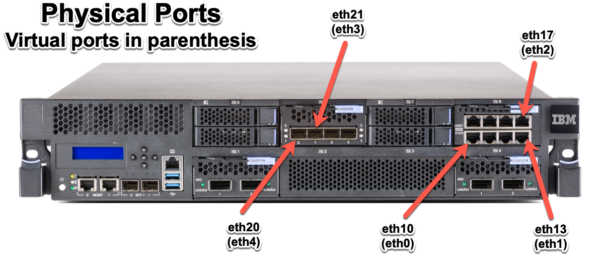
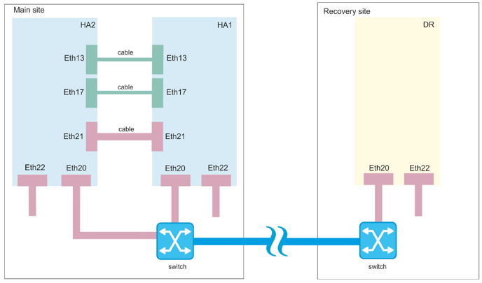
The M2002 introduced several additional network interfaces, including two new 2 x 40 GB QSFP+ ports as well as two additional 10GB SPF+ ports.
The MQ Appliance allows either a 10GB or 40GB Ethernet port to be used for replication on each appliance to configure DR. On the physical appliance that port by default is eth20, on the virtual appliance it is eth4.
Refer to IP Addresses in the Overview the IBM MQ Appliance PoT document, to determine the network adapters and IP addresses assigned to each appliance. Pay particular attention to eth4 as it is the adapter used for DR on the virtual appliance.
Start the Environment
-
Start the environment and wait until all three virtual machines have started. You may shut down MQAppl4, MQApp5,MQAppl6, and MQAppl7 as they will not be used in this lab.
-
The MQ appliances will have fully started when they reach the login prompt.
Configure Hardware for Disaster Recovery
In this activity, you will verify the hardware configuration necessary to connect the two appliances via the network.
-
Select the first appliance (MQAppl1) to access the console and login using the administrator credentials, user-id admin and password passw0rd.
-
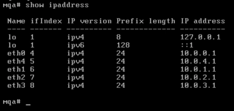
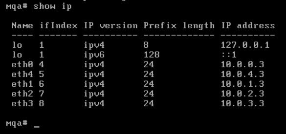
Issue the show ip command to display the list of the Ethernet interfaces and their IP assignments (ensure you are at the mqa# prompt).
-
Take note of the IP addresses for both eth0 and eth4. The other IP addresses are not used for Disaster Recovery.
Note that your IP addresses may be different than the ones shown above.
-
Repeat this on MQAppl3 and record the addresses.
Configure Disaster Recovery Queue Managers
In this activity, you will perform the configuration to make a queue manager part of a disaster recovery configuration.
A disaster recovery configuration is setup by defining a primary and secondary queue manager. The primary appliance is MQAppl1 and the secondary appliance is MQAppl3. You will use existing queue manager QM1. During the configuration, the queue manager must be in a stopped state.
-
Switch to the Windows VM and start a Firefox web browser using the icon on the Desktop.

-
Enter the IP address for MQAppl1 (https://10.0.0.1:9090) to log onto the MQ console.

Note: If you get a warning about a potential security risk, click the Advanced… button, then click Accept the Risk and Continue.
-
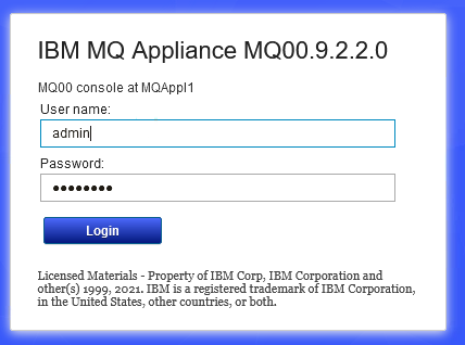
Sign in with admin / passw0rd.
We will use QM1 which was created previously.
QM1 uses port 1414 and has a file system size of 2GB. Remember that the available file system on the virtual appliance is very limited.
-
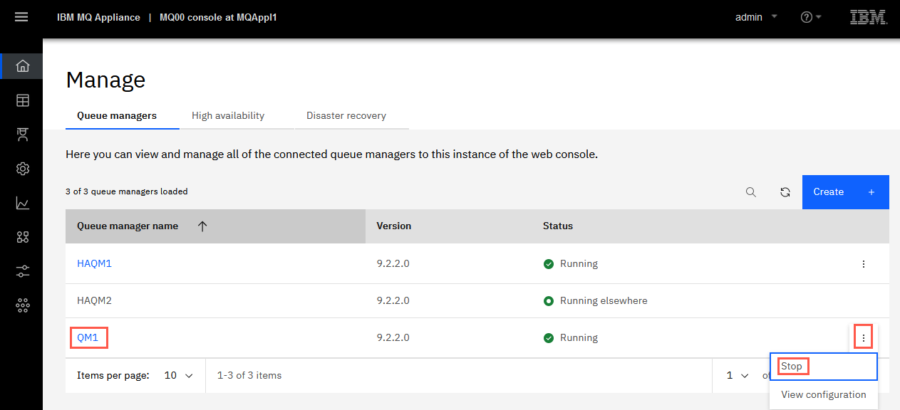
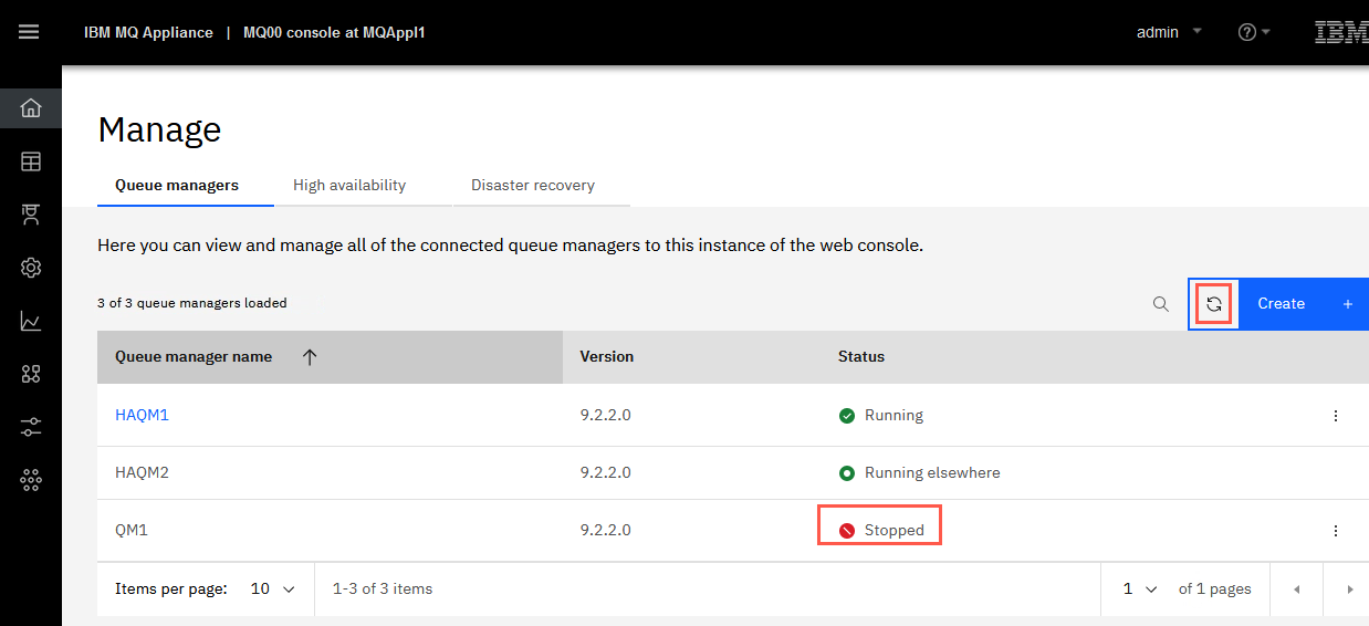
To prepare the disaster recovery configuration, the queue manager must be stopped. If QM1 is running, highlight it in the Manage > Queue Managers page and stop it by clicking the elipsis and select Stop.
-
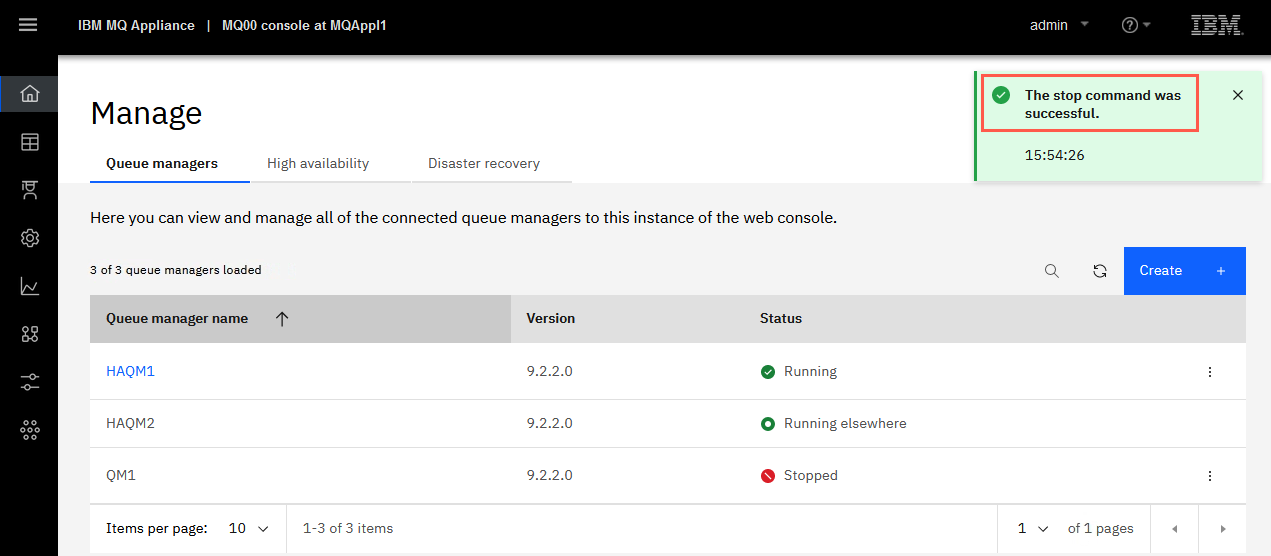
You receive a green confirmation that the command was successful.
-
Refresh the queue manager status to make sure it is stopped.
-
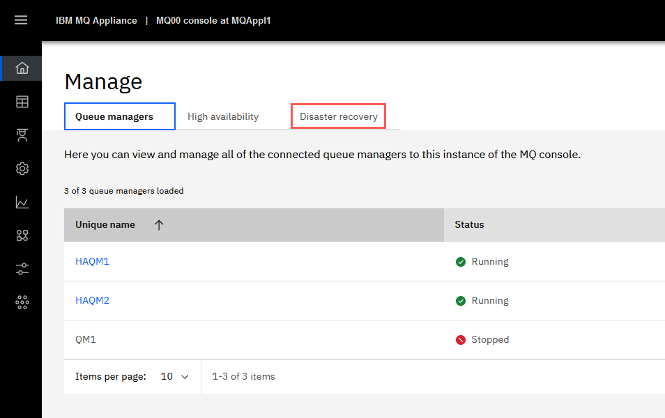
Click the Disaster recovery.
-
Click the
 icon for QM1 and select Configure DR.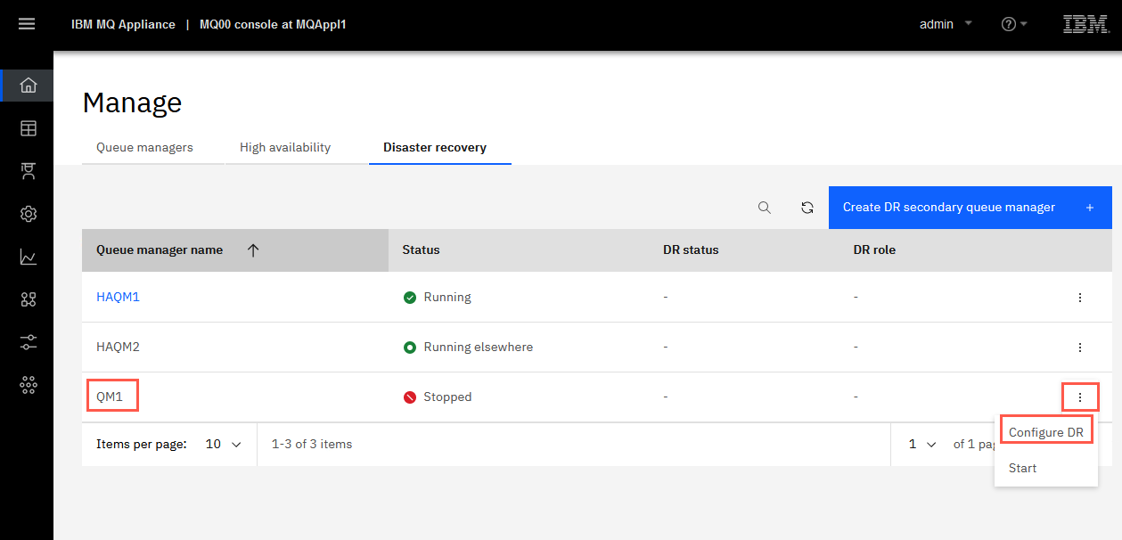
-
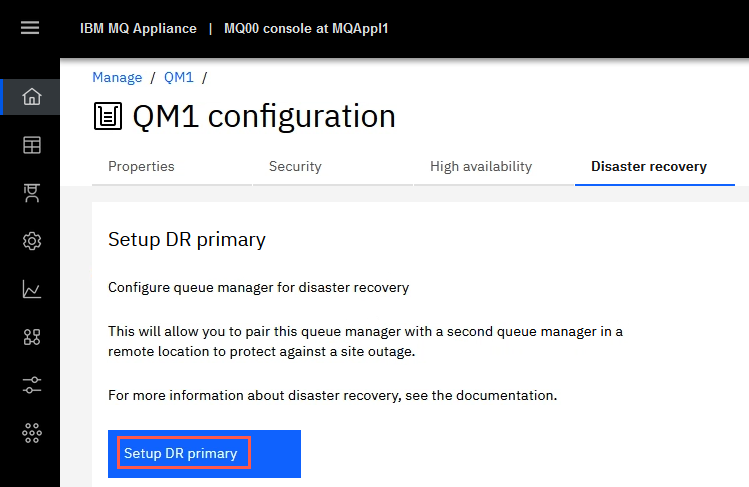
Click the Setup DR primary option.
-
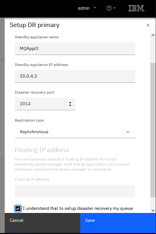
MQAppl3 will be the recovery appliance, so fill in the fields as shown below:
Standby appliance name: MQAppl3
Standby appliance IP address: 10.0.4.3 (or appropriate eth4 address of MQAppl3)
Disaster recovery port: 2014
Replication type: Asynchronous
Floating IP address: not configured
Click the checkbox to agree.
 Note:
Note:
10.0.4.3 is the IP address of eth4 (physical eth20) network adapter on MQAppl3 (refer to table at the top of this guide). -
Click Save.
Note:
The information used to generate the command:
crtdrprimary -m QM1 -r MQAppl3 -i <MQAppl3-eth4-IP_Address> -p 2014
* The queue manager name (-m) is passed to the command along with the name (-r) and IP address (-i) of the secondary (recovery) appliance. A port number (-p) used for replication must be specified.
* The port number must be in the 1025-9999 range, unused, but not 2222.If the command is successful, you will receive a green message indicating that the queue manager is prepared for disaster recovery replication.
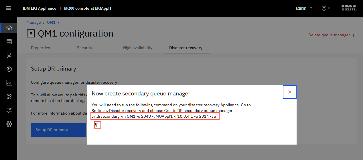
On successful completion of the command, the command generates and outputs the associated crtdrsecondary command to be run AS IS on the secondary (MQAppl3) appliance.
Use the copy icon to copy the command in the pop-up “Create DR secondary command” box, as you will need to run it on the recovery appliance MQAppl3.
-
Close the pop-up.
If you receive the error below, contact your instructor for help in making space available.

-
Open a new browser tab and enter the IP address for MQAppl3 (https://10.0.0.3:9090) to log onto the MQ console.
Note: If you get a warning about a potential security risk, click the Advanced… button, then click Accept the Risk and Continue.

-
Log in with admin / passw0rd.
-
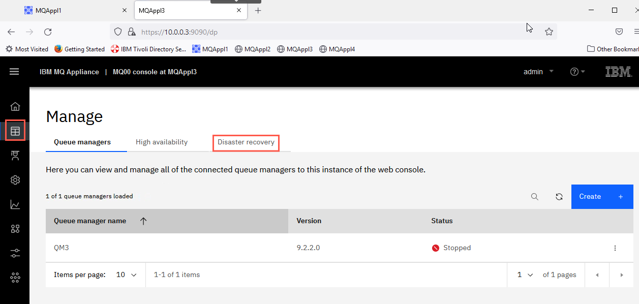
Click the Manage icon then Disaster Recovery button at the top of the page.
-
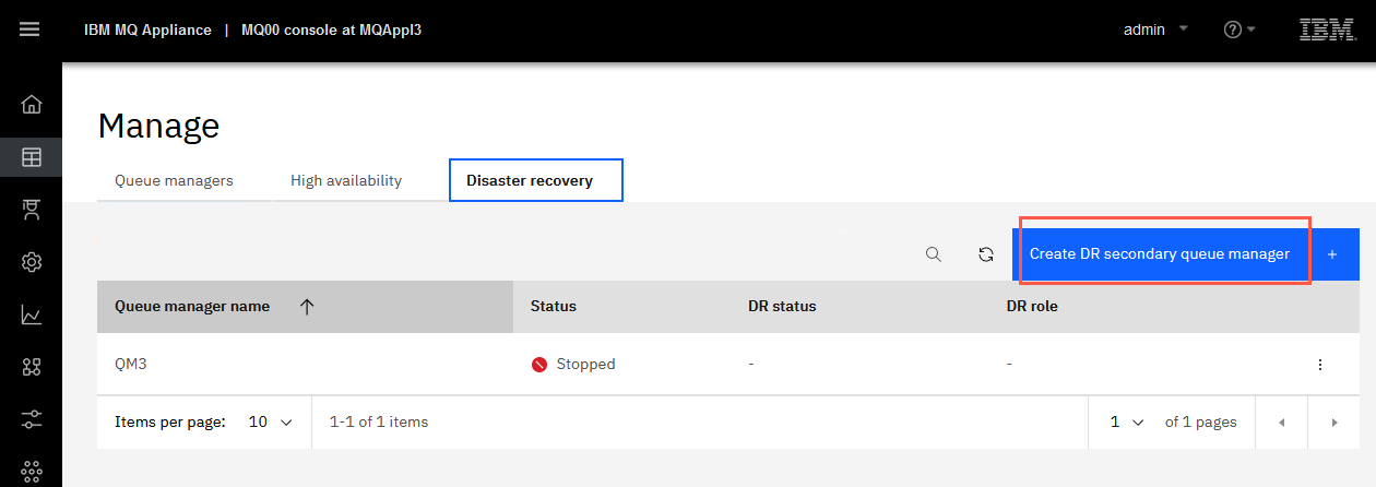
Click Create DR secondary queue manager.
-
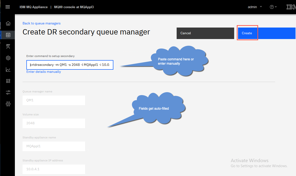
Paste the copied crtdrsecondary command in the “Enter command to setup secondary” box on appliance MQAppl3.
Once you paste the command, the other fields will automatically fill in.
For example: crtdrsecondary -m QM1 -s 2048 -l MQAppl1 -i 10.0.4.1 -p 2014
-
Click Create.
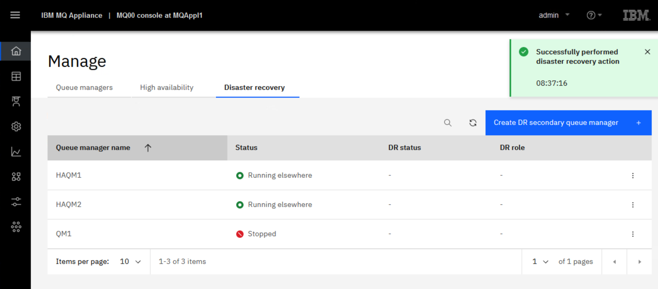
You should see a green confirmation box at the top of the console.
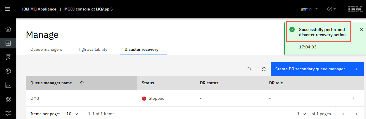
You can click the X to dismiss the box.
-
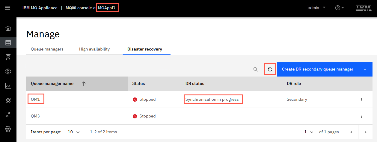
You should see QM1 show up in the Queue Managers with status Stopped. Notice that the DR Status is Synchronization in progress. You may need to click the refresh button for Queue Managers if you get an error message.
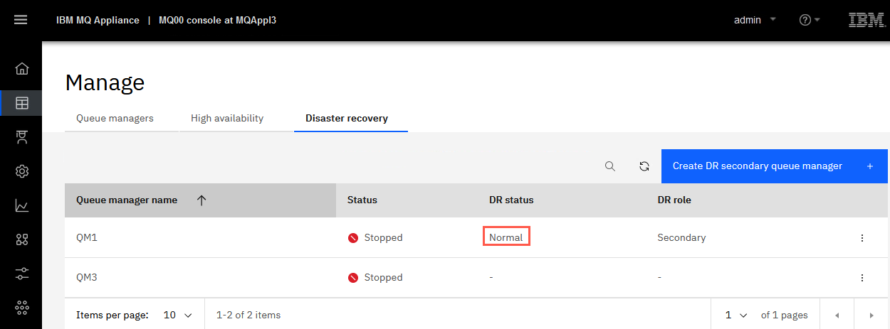
Once synchronization is complete the DR status will change to Normal.
 Note:
Note:
The information used to generate the command:
The crtdrsecondary command creates a secondary version of the queue manager on the recovery appliance in a disaster recovery configuration. All parameters are supplied by the equivalent crtdrprimary command and should be entered exactly as shown in the output from that command. After this command is run, synchronization of data from the main to the recovery appliance begins. The queue manager status is shown as stopped, and initial synchronization progress can be followed by using the status command. -
Run the status command to inquire about the synchronization status.
This command can be run on either appliance.
Remember you must be at the mqcli shell.
Command entered on MQAppl3:
status QM1
Command entered on MQAppl1:
status QM1
-
While at the MQAppl1 appliance command line, start queue manager QM1 on appliance MQAppl1 in mqcli mode:
strmqm QM1
The DR configuration for queue manager QM1 is now complete. From this point on, both MQ definitions and data are asynchronously replicated to the secondary appliance.
Perform a Disaster Recovery Test
In this activity, you will perform a Disaster Recovery test to validate the disaster recovery configuration that you just put in place.
The test includes the following steps:
-
Create a messaging user-id
-
Generate some MQ object definitions for the messaging application
-
Generate some persistent message traffic to queue manager QM1
-
Shutdown of the primary MQAppl1 appliance
-
Recovery of the QM1 queue manager on the secondary MQAppl3 appliance
-
Get messages previously sent from queue manager QM1
Now let’s start the test.
-
Return to the MQAppl1 appliance.
-
Create a messaging user on the appliance
usercreate -u potuser -g users
If you receive an AMQ6618: The userid ‘potuser’ already exists message, you can ignore it and continue.
Note:
The commands are stored in a text file in C:\Lab08\Commands\Commands Snippets.txt.
You may copy and paste the commands if you don’t want to type them. However, you cannot paste in the mqcli command line, so you will need to log on to the appliance using putty, which will allow you to paste the commands. -
Create some MQ objects on the appliance with the following commands:
 runmqsc QM1

 def channel(APP.CLIENT) chltype(SVRCONN)

 def ql(TEST.Q)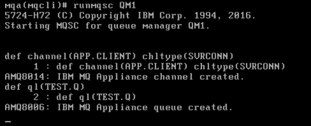
-
Grant authorizations to the MQ objects on the appliance.
 set authrec objtype(qmgr) principal('potuser')
 authadd(connect,inq)

 set authrec objtype(queue) profile(TEST.Q)
 principal('potuser') authadd(put,get)

 end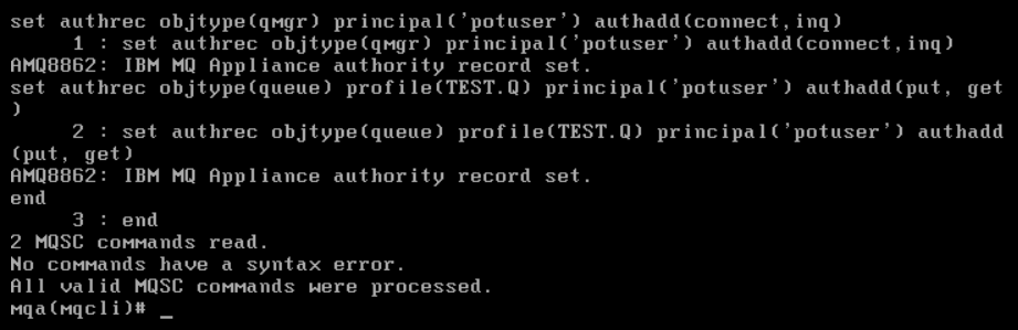
-
Switch to the Windows environment (Windows 10 x64) and double click the potuser icon. This will open a Windows command prompt.

-
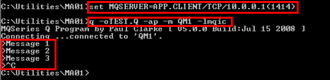
Send some persistent messages to queue manager QM1.
From the Windows command prompt:
 cd \Utilities\MA01

 set MQSERVER=APP.CLIENT/TCP/<MQAppl1-eth0-IP>(1414)
Replace <MQAppl1-eth0-IP> with the correct IP address – normally 10.0.0.1.
-
Now we use the q program to put some persistent messages.
q -o TEST.Q -ap -mQM1 -lmqicparameters:
-o output queue name (small o)
-a options: p=persistent
-l library: mqic=32bit (small l)
-
Enter three messages.
-
Finally, CTRL-C out of the program.
-
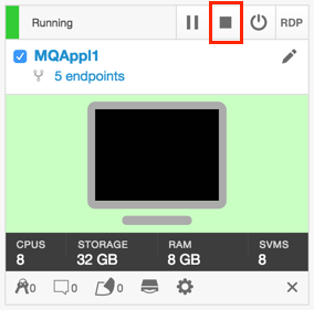
Shut down the MQAppl1 appliance using the Skytap dashboard shutdown button. Wait a minute or so for the action to work.
-
Switch to the MQAppl3 appliance and display the status of queue manager QM1.
status QM1
You should see a DR status now of Remote appliance(s) unavailable as the unavailability of MQAppl1 is recognized.
If you do not see this status, wait a few seconds and try again.
-
In the browser session for MQAppl3, notice that QM1 is still Stopped. The DR functionality does not automatically start the queue manager.
Click
for QM1 and select Configure DR. Select DR Status.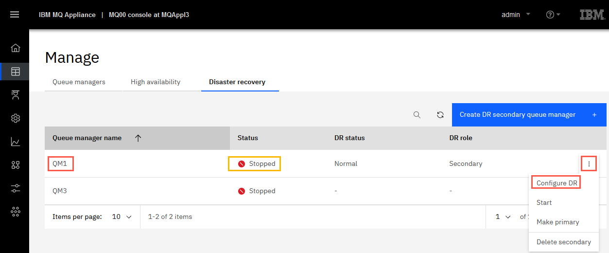
-
Make queue manager QM1 on MQAppl3 primary.
Click Make primary.
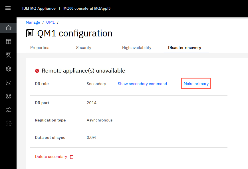
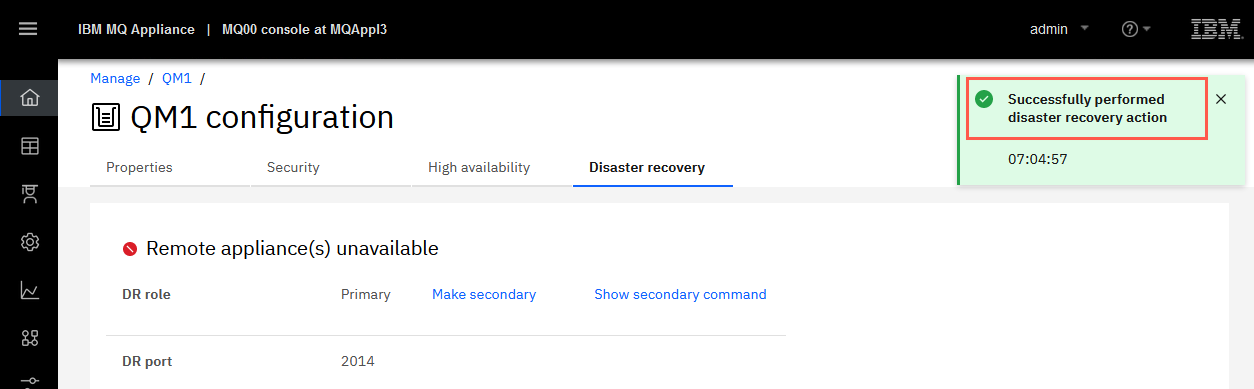
Click Confirm to make QM1 DR primary.
You should receive a green bar with the Successfully performed disaster recovery action message. You can click on the X to dismiss the message.
OR
You can also run the command from the MQAppl3 command line, enter the command:
makedrprimary -m QM1
-
Start queue manager QM1 on MQAppl3.
From the web browser tab for MQAppl3 MQ Console:
Click the Manage breadcrumb to return to Manage Queue managers. Click the
button for QM1 and select Start.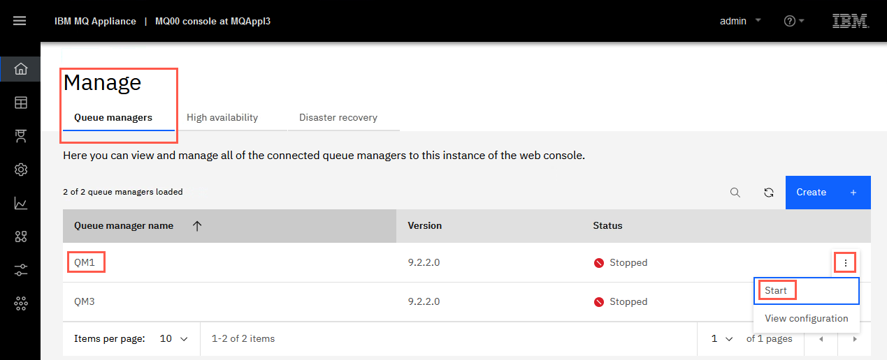
OR
From the command line:
strmqm QM1
The queue manager has now been recovered on the secondary appliance and it is ready to accept connections and process messages.
-
Switch back to the Windows environment (Windows 10 x64) browser session for MQAppl3 if necessary.
-
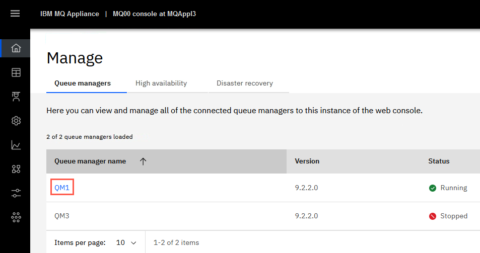
Click the hyperlink for QM1.
Note that QM1 still has three messages on the TEST.Q.
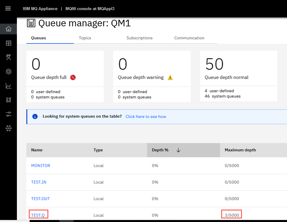
There may be messages on other queues left from previous labs too.
-
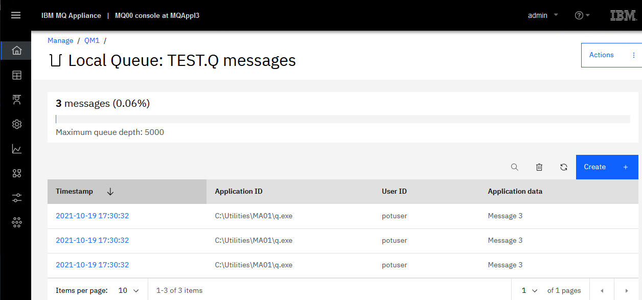
Browse the messages by clicking the hyperlink for TEST.Q.
These messages will look familiar, as they are the ones you created on QM1 on MQAppl1.
-
Click Close.
-
Retrieve messages previously put to the TEST.Q queue.
Return to the Command Prompt and repoint the MQSERVER variable to the recovery appliance (at your eth0 IP address).
set MQSERVER=APP.CLIENT/TCP/<MQAppl3-eth0-IP>(1414)Replace <MQAppl3-eth0-IP> with the correct IP address – normally 10.0.0.3.
Retrieve the messages:
q -ITEST.Q -mQM1 -lmqicparameters:
-I input queue name (capital i)
-a options: p=persistent
-l library: mqic=32bit (small l)

OOPS! What happened? 2035… Security error, not authorized! Let’s investigate….
-
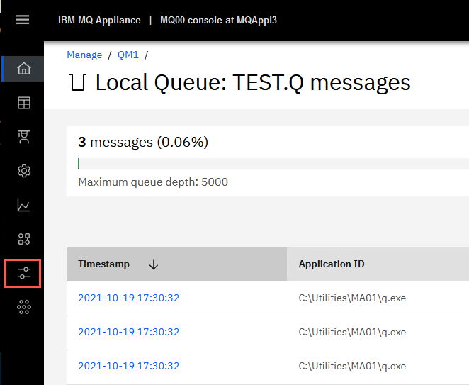
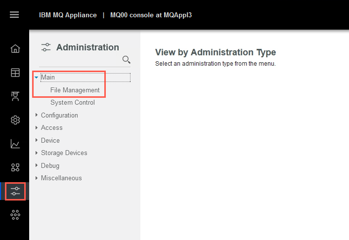
On MQAppl3’s MQ Console, click the Administration icon.
-
Expand the Main tab and select File Management.
-
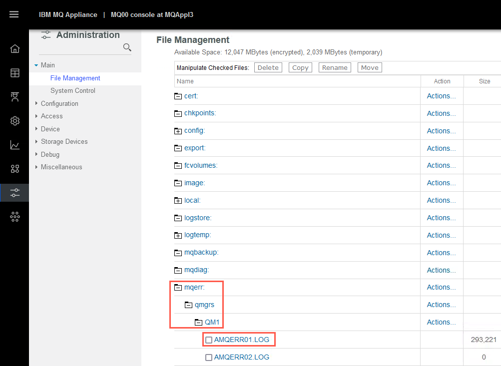
Navigate to mqerr: > qmgrs > QM1, then click on AMQERR01.LOG. The log file opens in a new tab in your browser.
-
Scroll to the bottom and review the error.
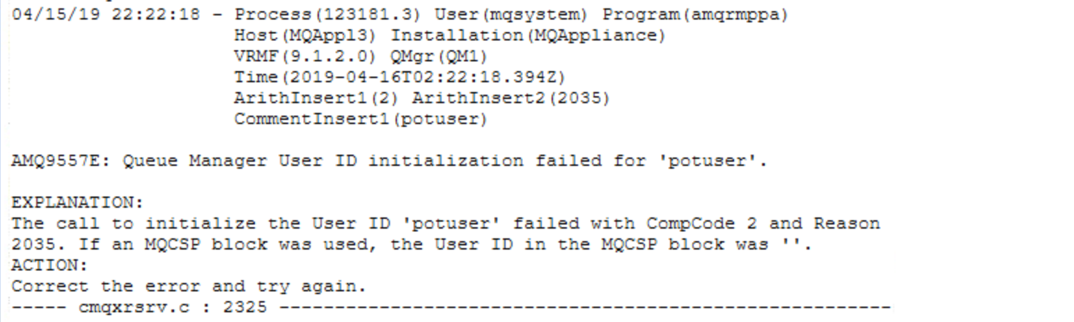
The problem is that messaging users are not replicated and must be re-created during DR time. Note that MQ authorizations are part of the queue manager and are replicated.
-
Close the error log by closing the browser tab.
-
Re-create the messaging user-id potuser on MQAppl3.
Switch back to the MQAppl3 command line and enter:
usercreate -u potuser -g users
-
Switch back to the Windows environment.
-
Again attempt to retrieve the messages in the potuser command session:
q -ITEST.Q -mQM1 --lmqicparameters:
-I input queue name (capital i)
-a options: p=persistent
-l library: mqic=32bit (small l)
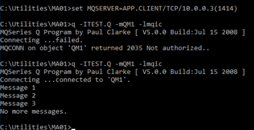
Voila! The DR test is successful and complete!
Remove a queue manager from a disaster recovery configuration
-
Switch to the MQAppl3 browser tab and click the Manage icon.
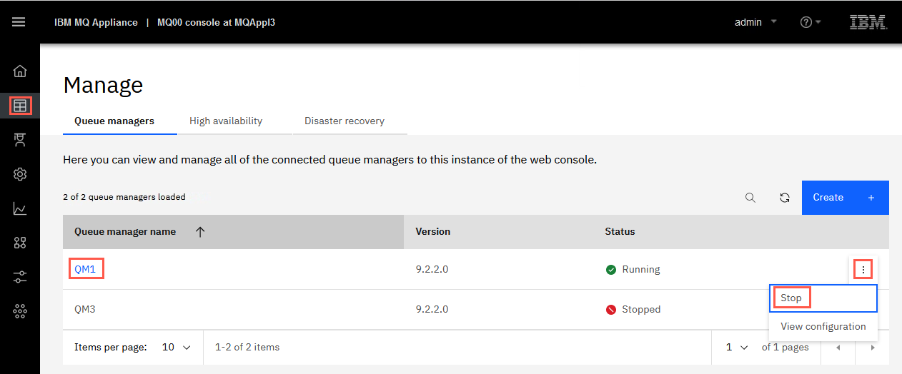
Stop queue manager QM1, by clicking the elipsis and select Stop.
-
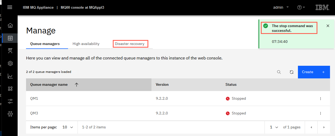
You receive confirmation of the stop action.
Then click Disaster recovery.
-
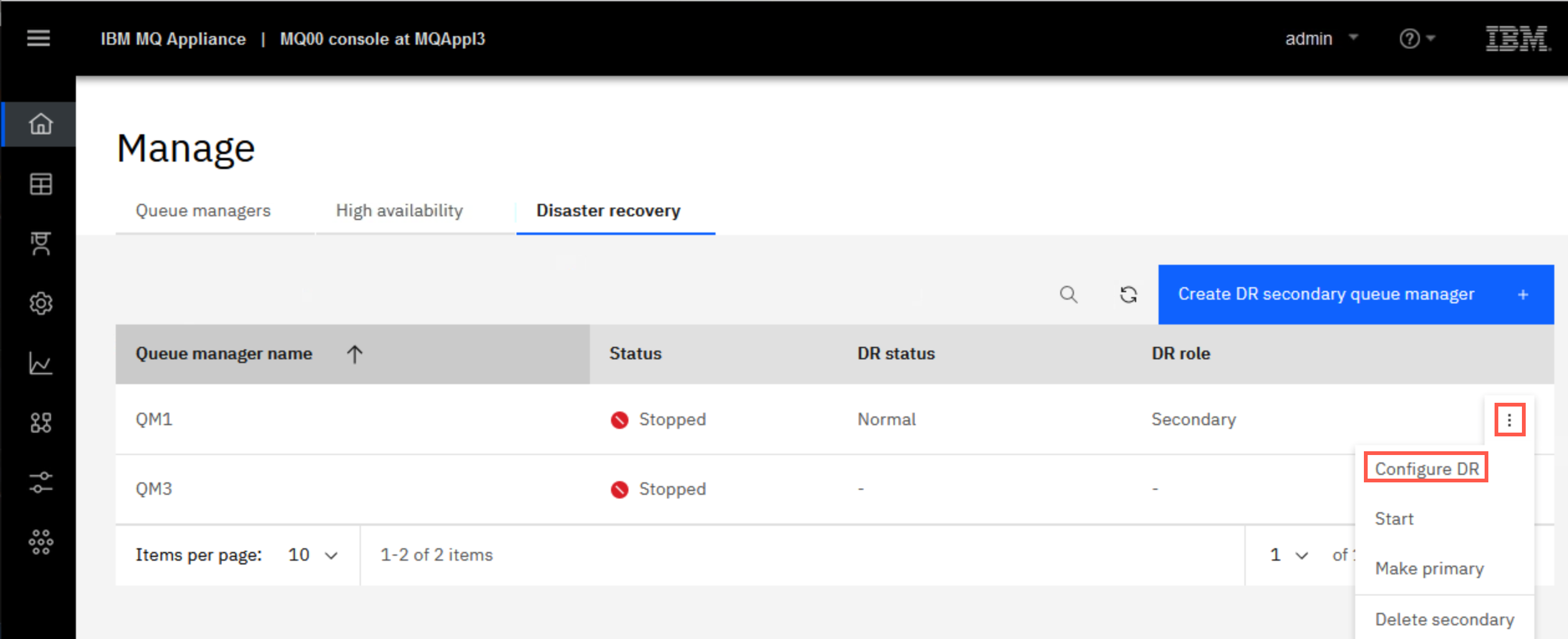
Click the elipsis for QM1 and select Configure DR.
Click Make secondary.
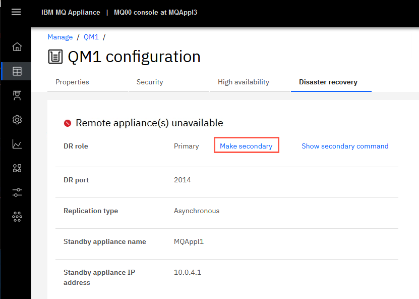
Click Confirm on the pop-up to make QM1 secondary.
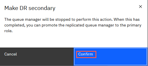
You receive the green confirmation pop-up.
-
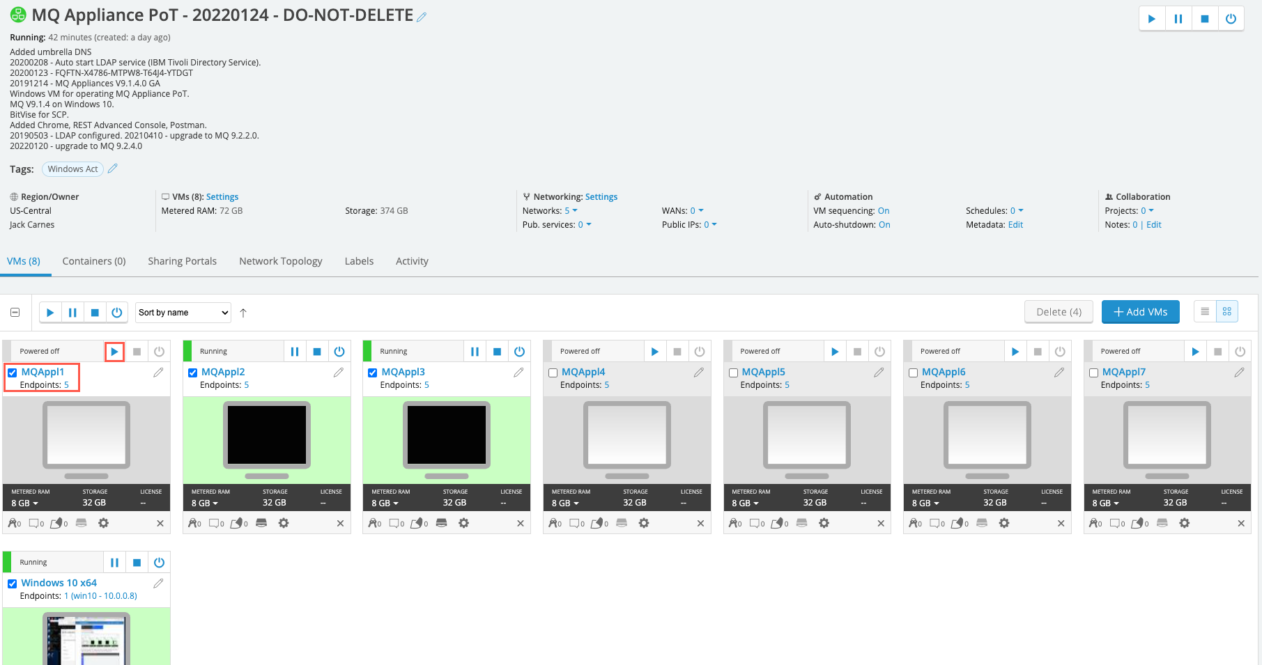
From the Skytap dashboard, start MQAppl1.
-
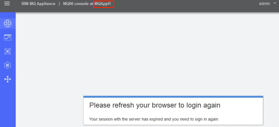
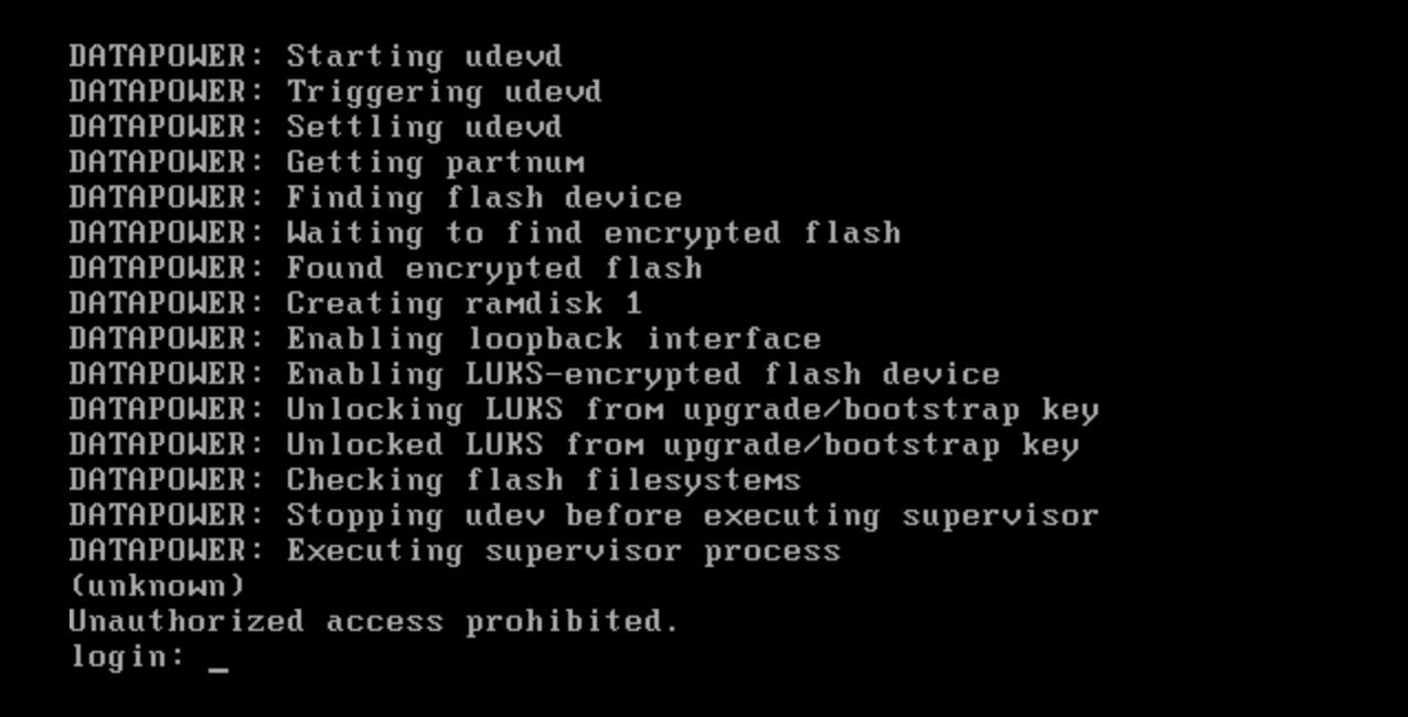
Return to browser tab for MQAppl1. Wait for MQAppl1 to initialize. You will know initialization is complete when the login: prompt is displayed on the MQAppl1 console or you are prompted to refresh the browser on the MQAppl1 browser tab.
-
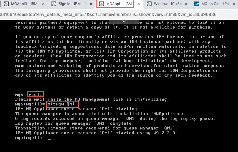
Login and start QM1 on MQAppl1.
-
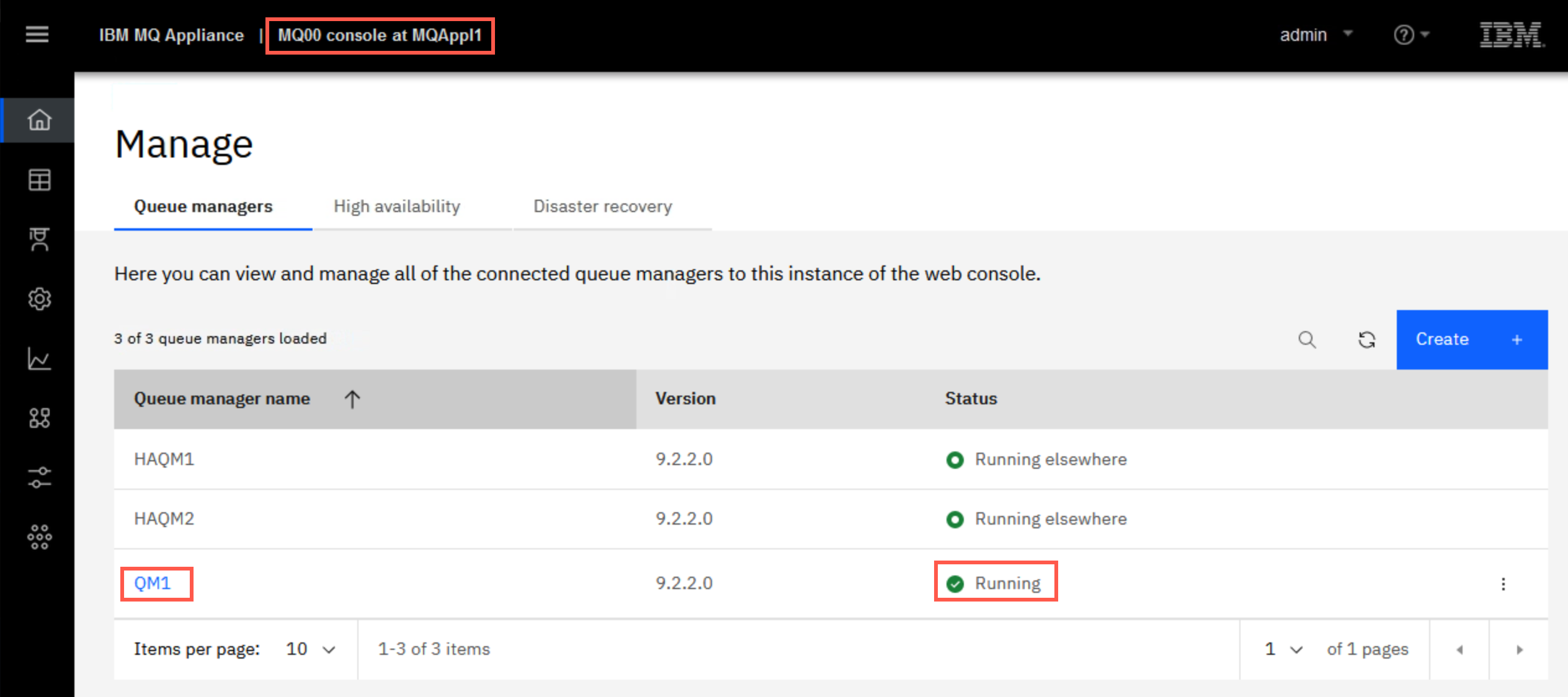
On the Windows VM, return to the browser tab for MQAppl1. You will be required to sign-in again since MQAppl1 was restartred. Click Manage. QM1 will display a Starting status, then Running.
-
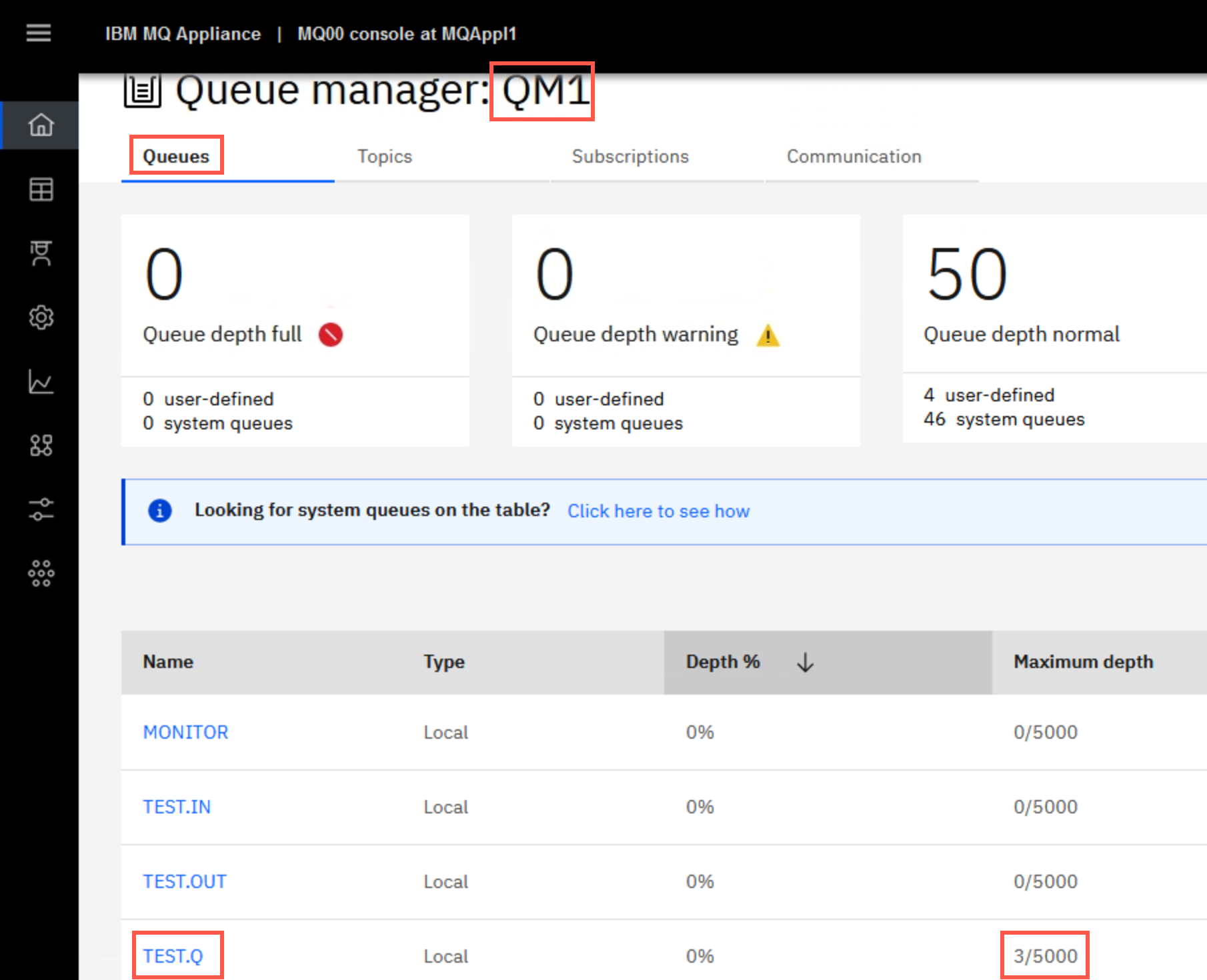
Click the hyperlink for QM1 then Queues. You will see that the three persistent messages are still on TEST.Q.
-
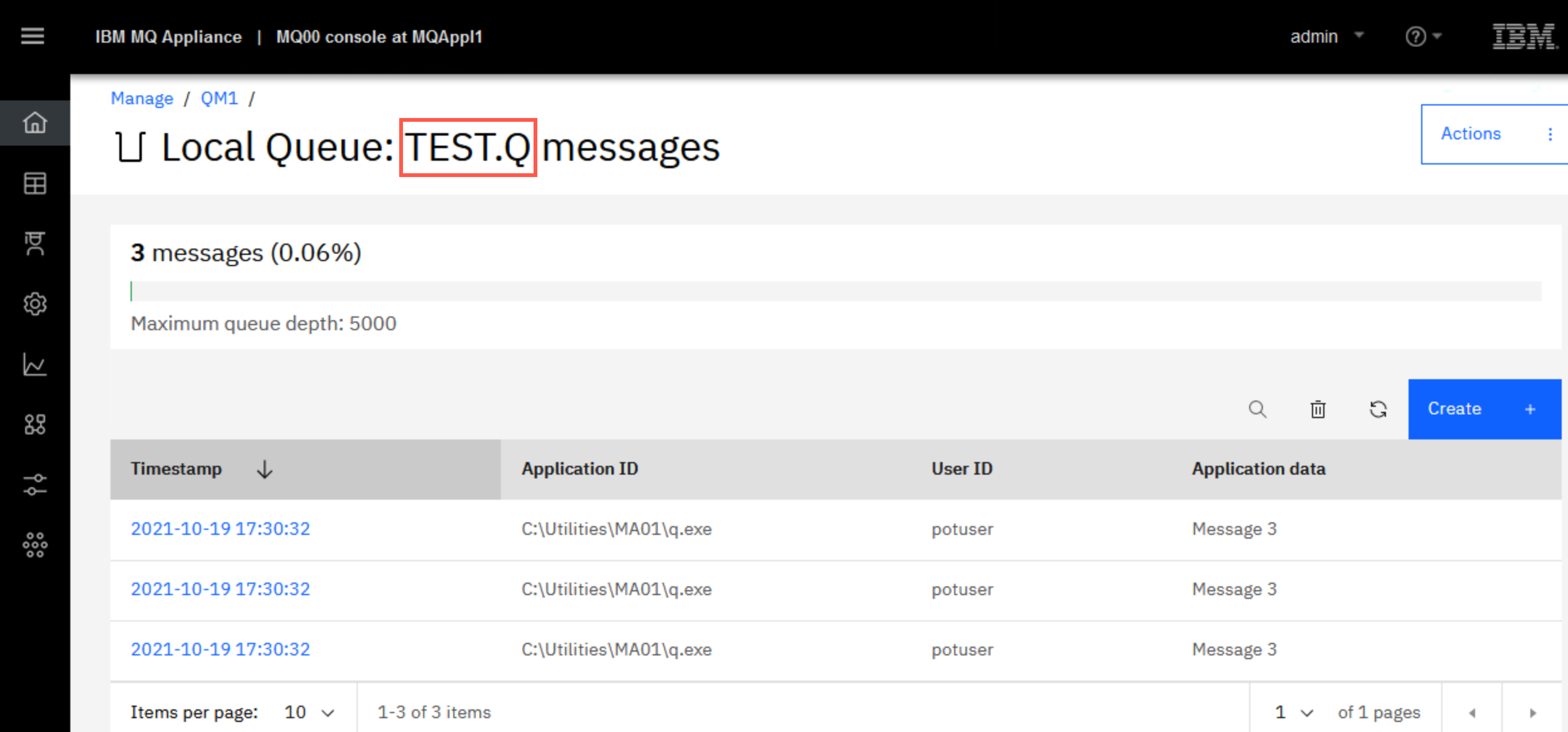
Click TEST.Q to browse the messages.
-
You have verified that your messages are still on TEST.Q on queue manager QM1 when QM1 has been restored on the main production appliance.
-
On MQAppl3’s MQ Console QM1 on the Disaster Recovery pane, Delete DR secondary.
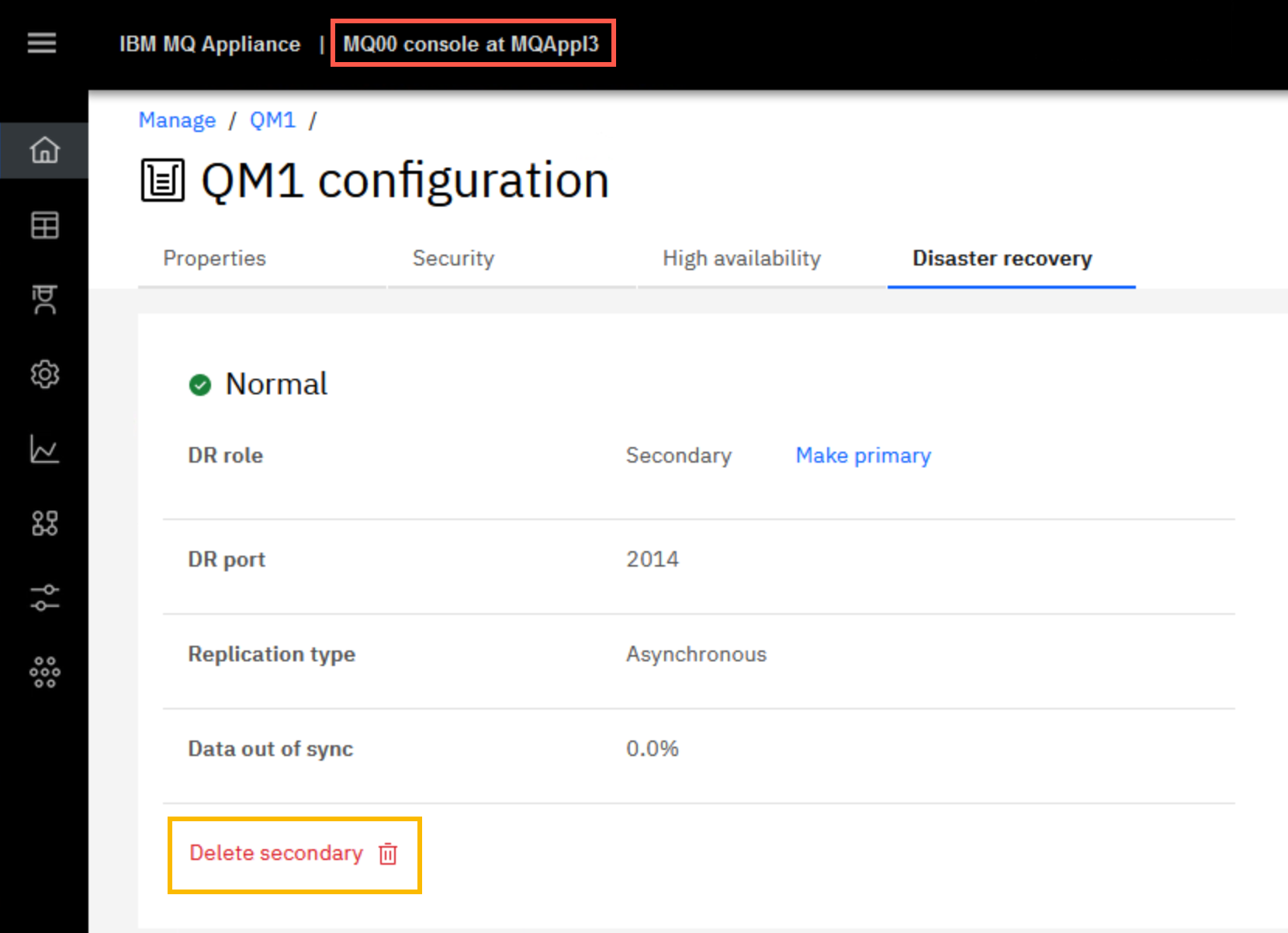
Click Confirm on pop-up.

You will receive the green succes message pop-up. Click the X to dismiss the message.
-
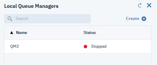
Wait a few seconds and you will see QM1 disappear from the MQ Console. QM1 has been removed from the disaster recovery configuration.
-
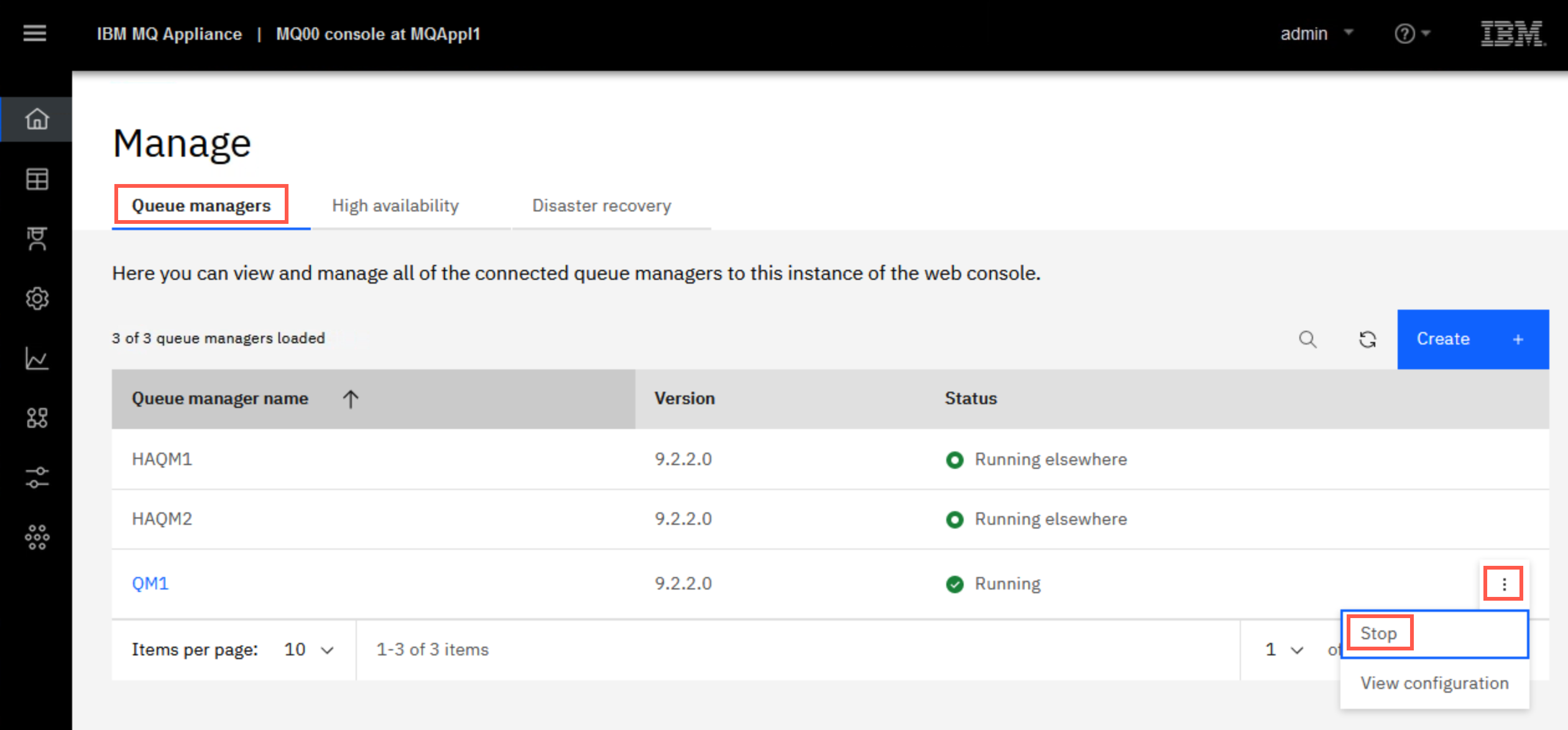
On MQAppl1’s MQ Console click the Manage breadcrumb, then Queue Managers. Click the elipsis for QM1 and select Stop.
-
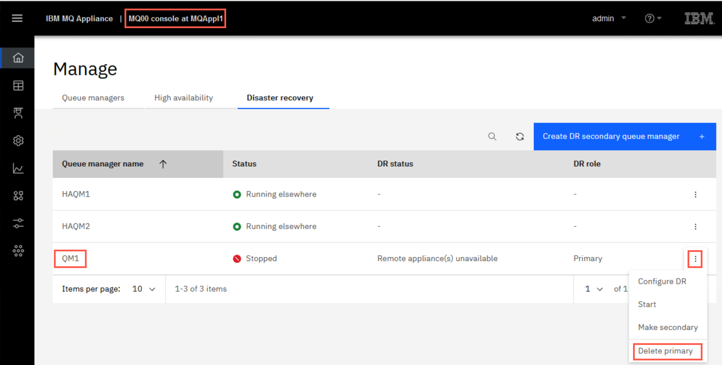
You will receive the green success pop-up and QM1 shows a Stopped status. Once QM1 is stopped click Disaster Recovery and then Delete primary.
-
You will receive the green successful operation message. QM1 is now completely removed from DR configuration on any appliance. Click the X to dismiss the message.
Configuring disaster recovery for a high availability queue manger
You can specify that a high availability queue manager also belongs to a disaster recovery configuration.
The following exercise provides insight into DR support for High Availability Queue Managers and allows us to explore recovery of Queue Managers running on designated HA appliances (e.g. at one site), to a remote Disaster Recovery site (until such point as the main site is recovered).
Both appliances in a high availability pair are typically located in the same data center. If some disaster befalls the data center, and both appliances are unavailable, you can manually start the queue manager on a recovery appliance located in another data center. In this environment, assume MQAppl3 is in another data center and will be the disaster recovery appliance.
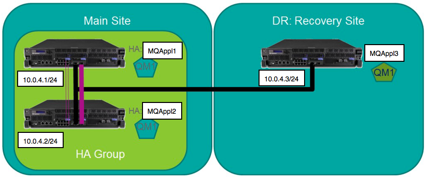
The MQ Appliance DR feature supports flexible DR topologies consisting of ‘live’ appliances at multiple sites. DR support is provided at the Queue Manager (QM) level, so they can be configured independently according to DR policy – e.g. using a simple main/recovery site DR strategy or multi-site main/recovery strategy.
Just one network connection is required for DR between the MQ Appliances hosting the Queue Managers. The appliances are designed to tolerate a level of network latency between distant sites – different than High Availability MQ appliances, which tend to be in close proximity, and are designed for automatic takeover with no data loss.
In a simple scenario, if a ‘main’ site fails, the recovery process begins to ensure business continuity. One or several of the Queue Managers on the ‘main’ appliance are to be recovered on a ‘recovery’ appliance, which could be many miles away. The secondary DR Queue Managers on the remote site are converted to Primary QMs and thus become Primary instances on the recovery appliance or appliances, as policy dictates. In the latest update to DR support, a HA Queue Manager (e.g. where the HA site is ‘taken out’) can be DR enabled and the HA site can be recovered to the designated recovery site.
Note that an appliance can support a mixture of HA, DR or standalone Queue Managers, which can co-exist quite happily.
Finally, it may be worth noting that ‘ports’ or ‘interfaces’ mentioned in this lab (e.g. eth0, eth4) are mapped different to those on the physical MQ appliance, that may be rack-mounted in the real world.
The diagram below provides a pictorial representation:
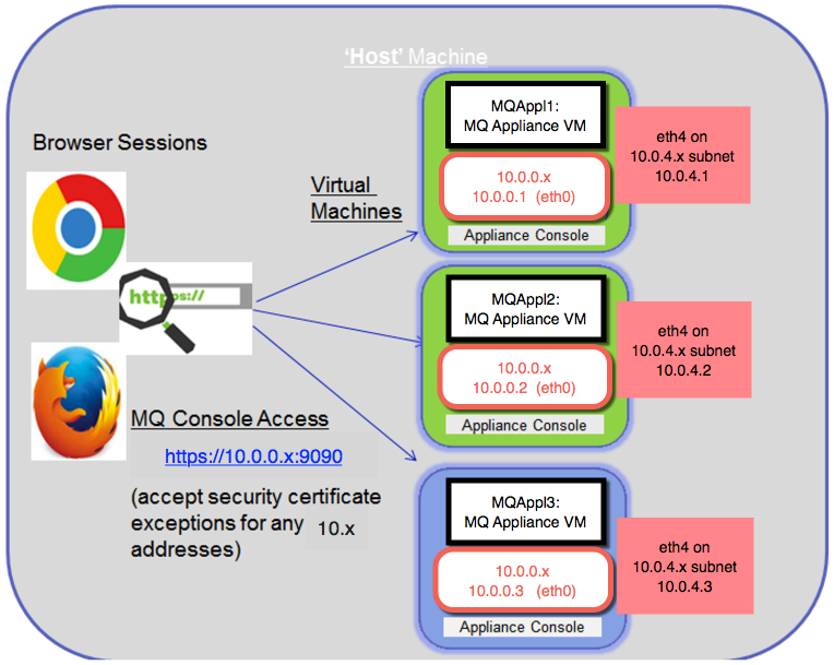
Note that on the physical MQ appliance, the physical port (interface) numbers are different to those ports shown in this hands-on lab, using the Virtual Appliance. The mappings of the virtual ports are in parentheses.
Disaster Recovery sequence of events
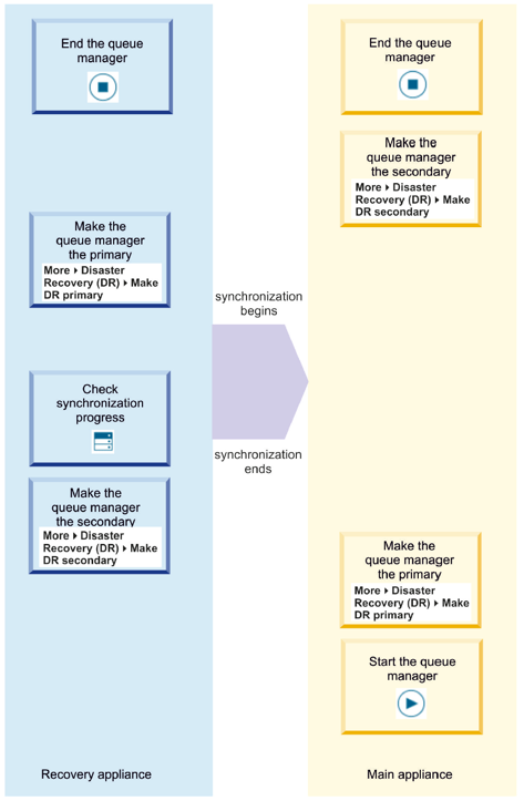
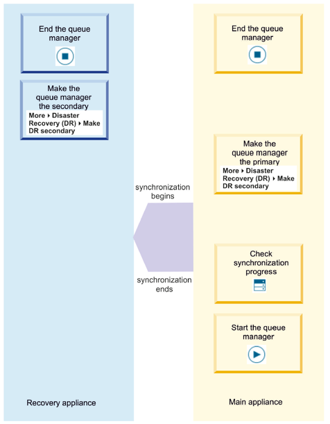
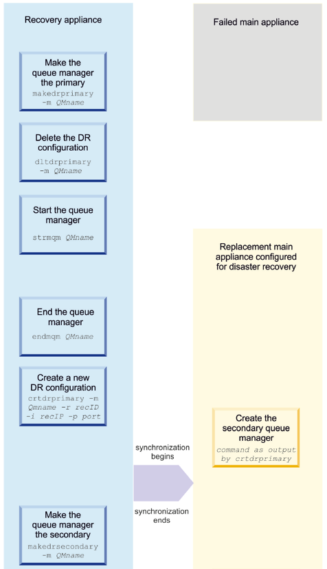
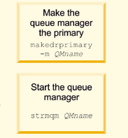
The following diagrams provide the detailed sequence of events in graphical form between the main appliance and fail over appliance in a disaster recovery configuration.
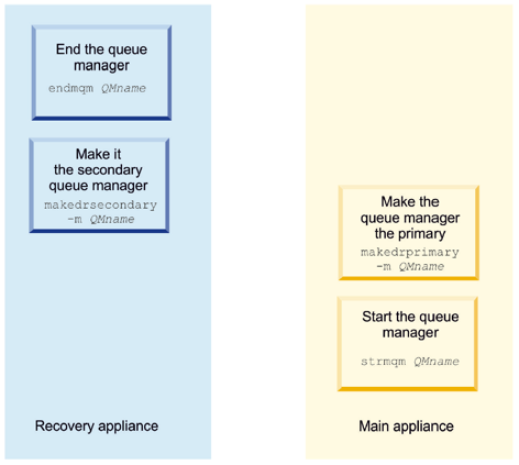
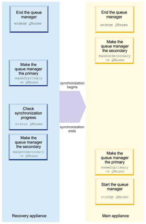
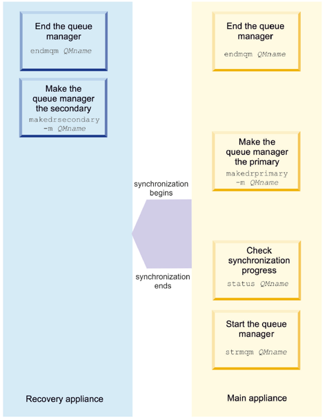
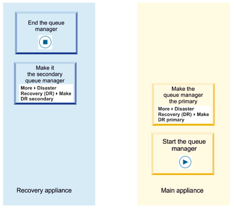
Prepare for HA group in DR configuration
If QM1 was deleted in the previous exercise, you can skip the first two-three steps (depending on if QM1 is deleted from both appliances).
-
Since space is limited on virtual appliances, you need to delete QM1 as we will not use it in this exercise and need the space.
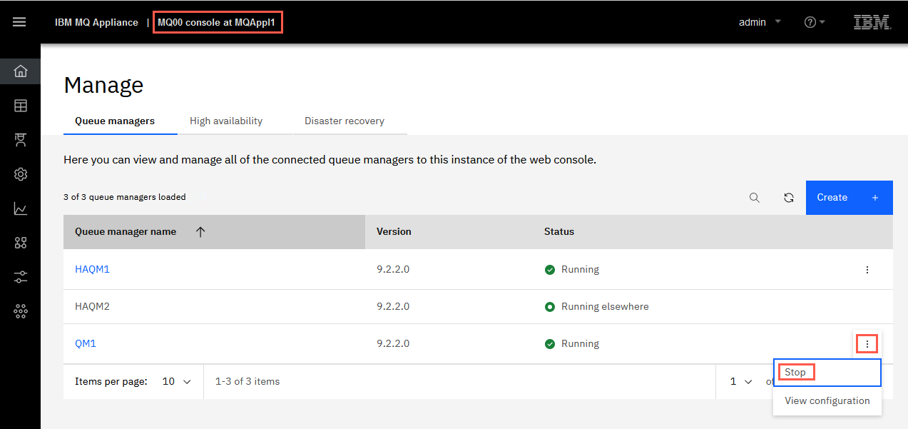
On MQAppl1, use the MQ Console and go to Manage > Queue Managers. Click the elipsis for QM1 and select Stop.
-
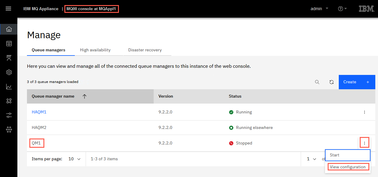
Once QM1 is stopped, click the elipsis again and select View configuration.
-
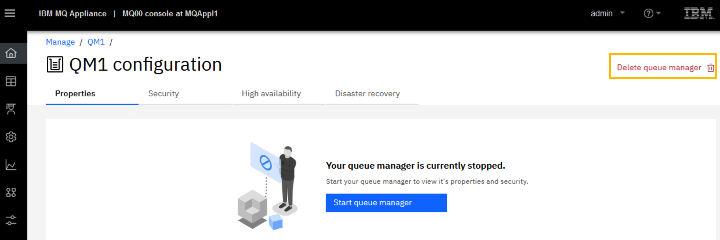
Click Delete queue manager.
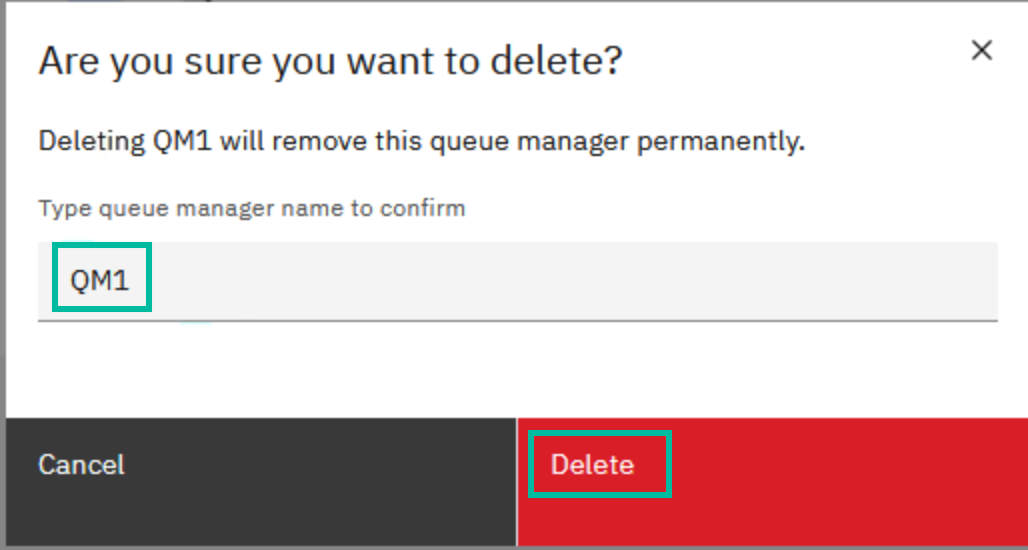
Type the name of queue manager and click Delete.
Refresh the page to see that QM1 has been deleted.
-
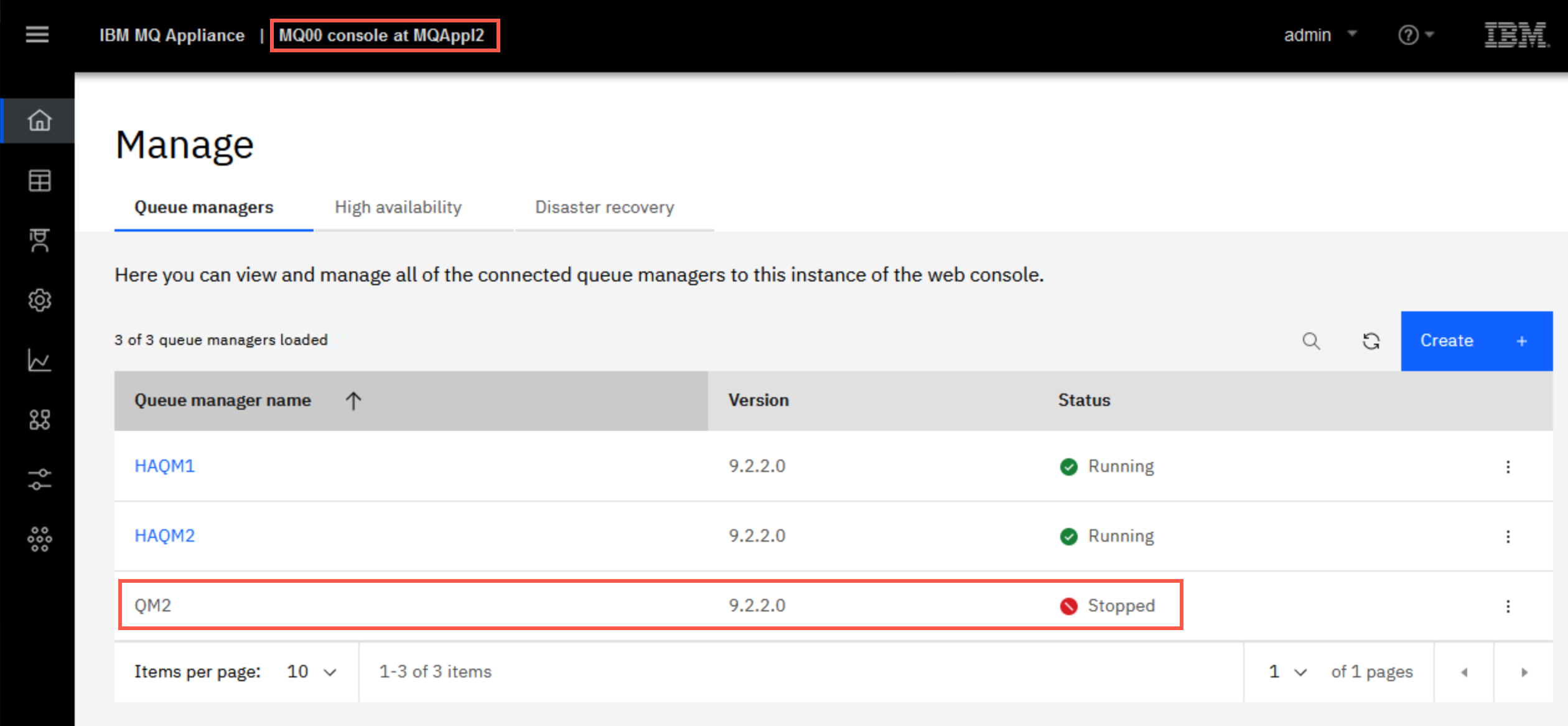
Logon on to the MQAppl2 MQ Console and repeat the previous step to delete the queue manager QM2 (if it exists) on MQAppl2. Make sure the only queue managers you see on MQAppl2 are HAQM1 and HAQM2. Delete any others.
-
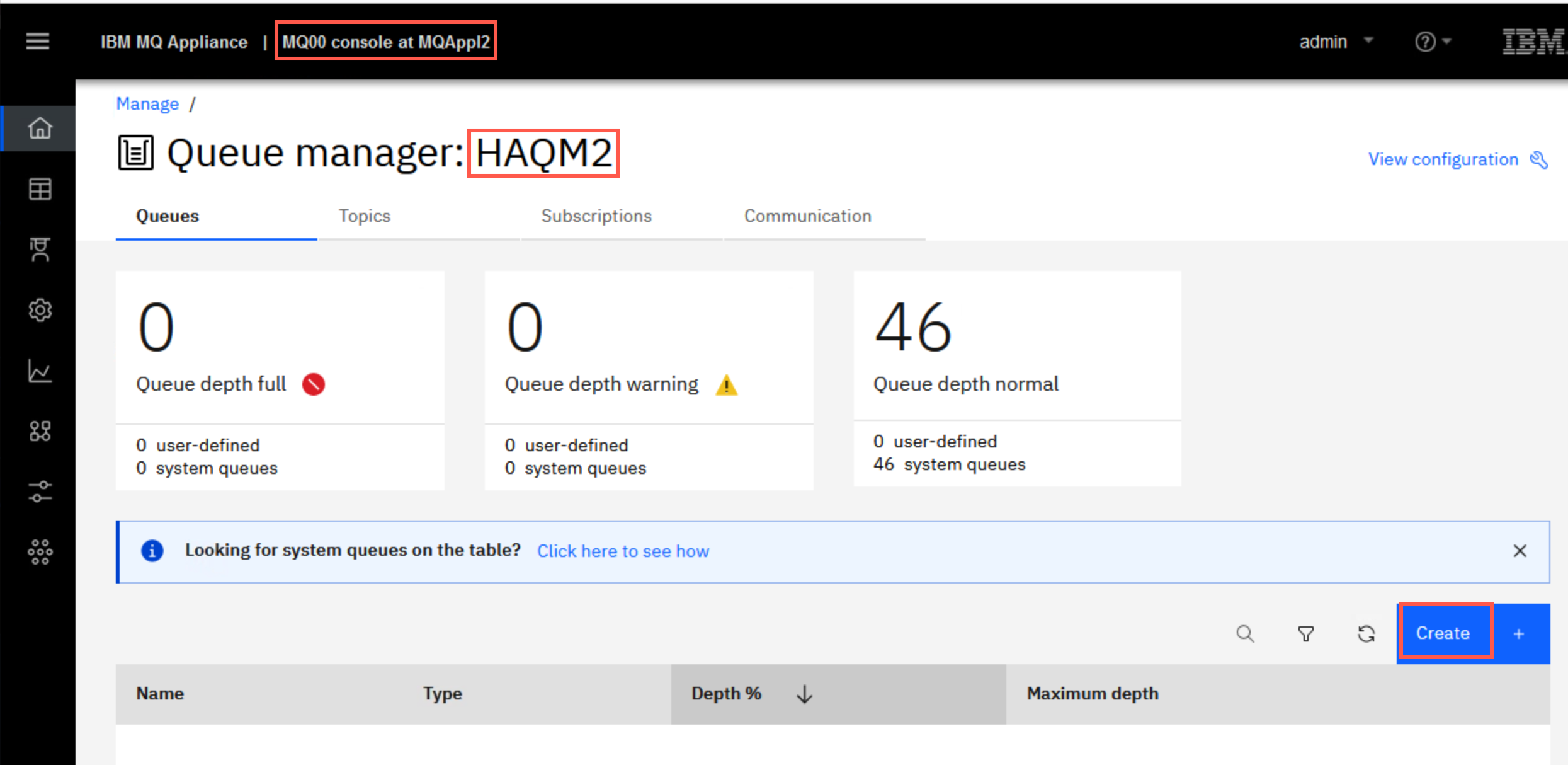
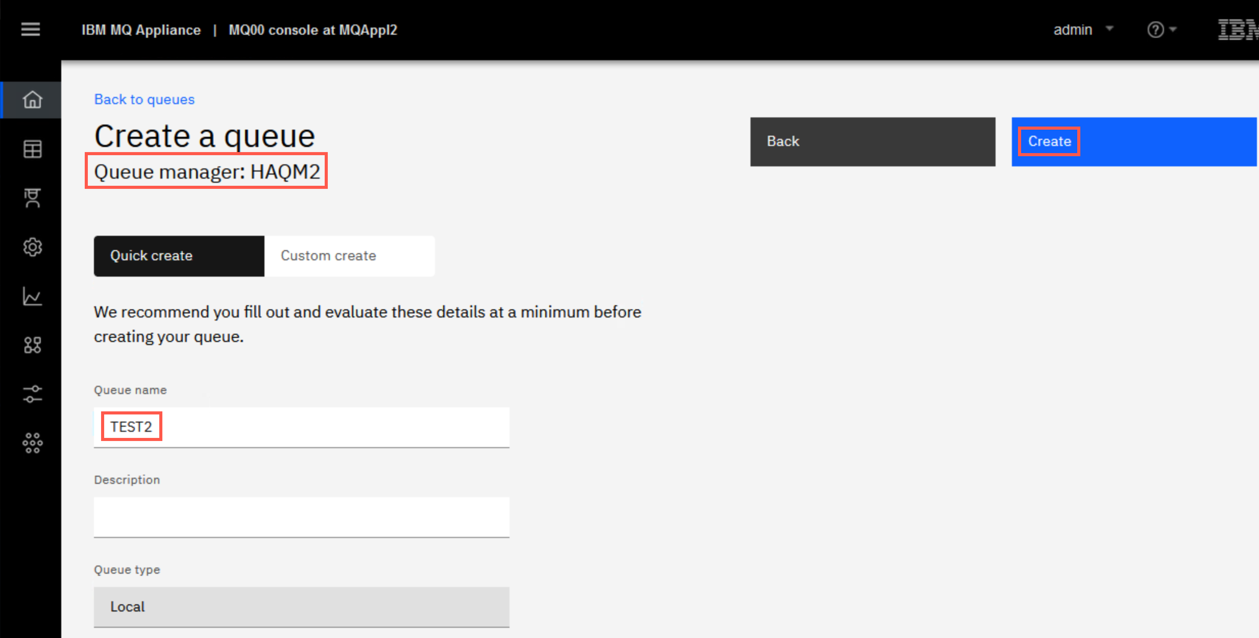
Staying on MQAppl2’s MQ Console, add a local queue named “TEST2” on queue manager HAQM2.
-
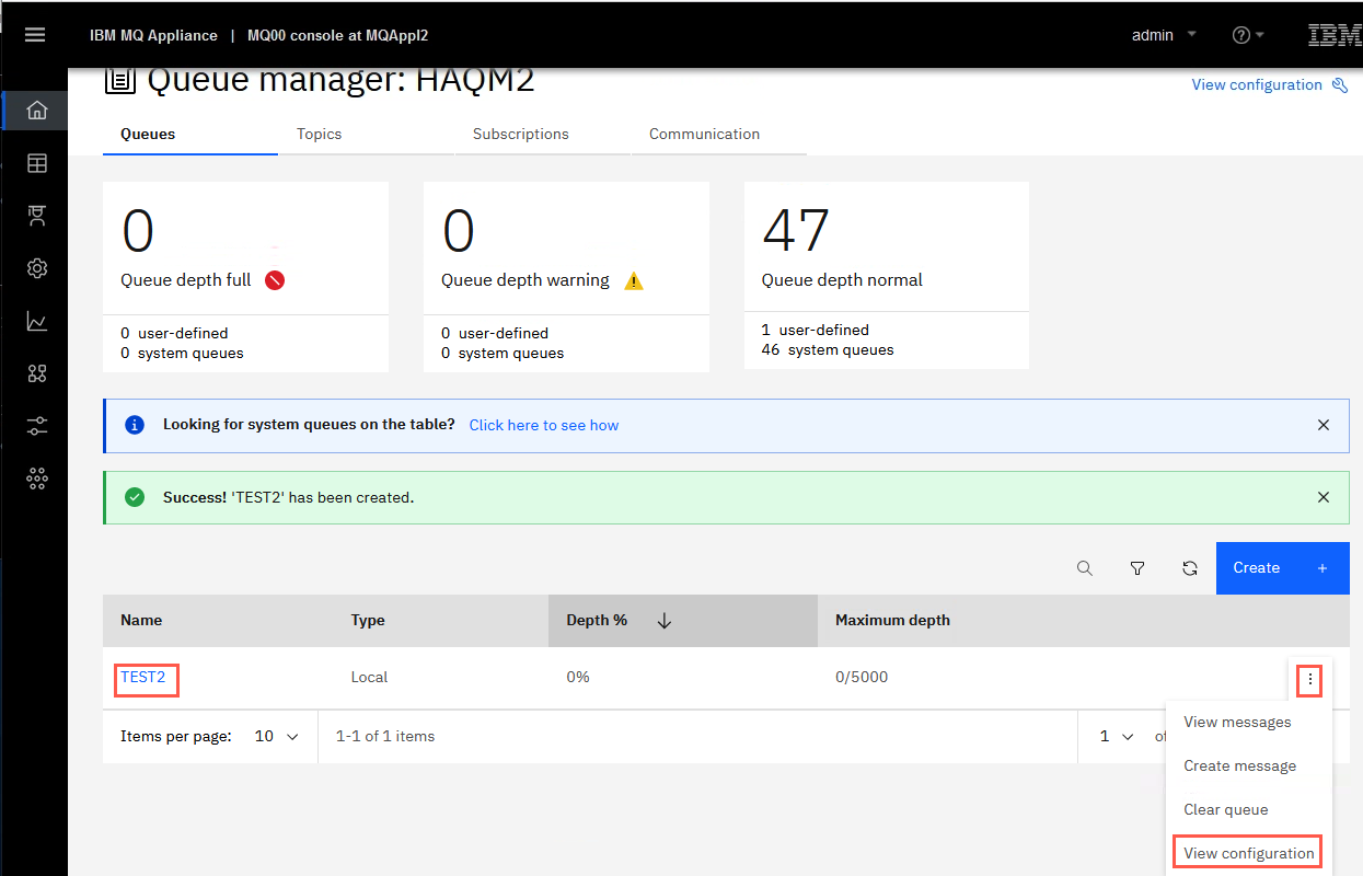
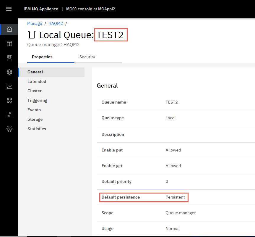
Open the properties for TEST2 by clicking the elipsis and select View configuration.
-
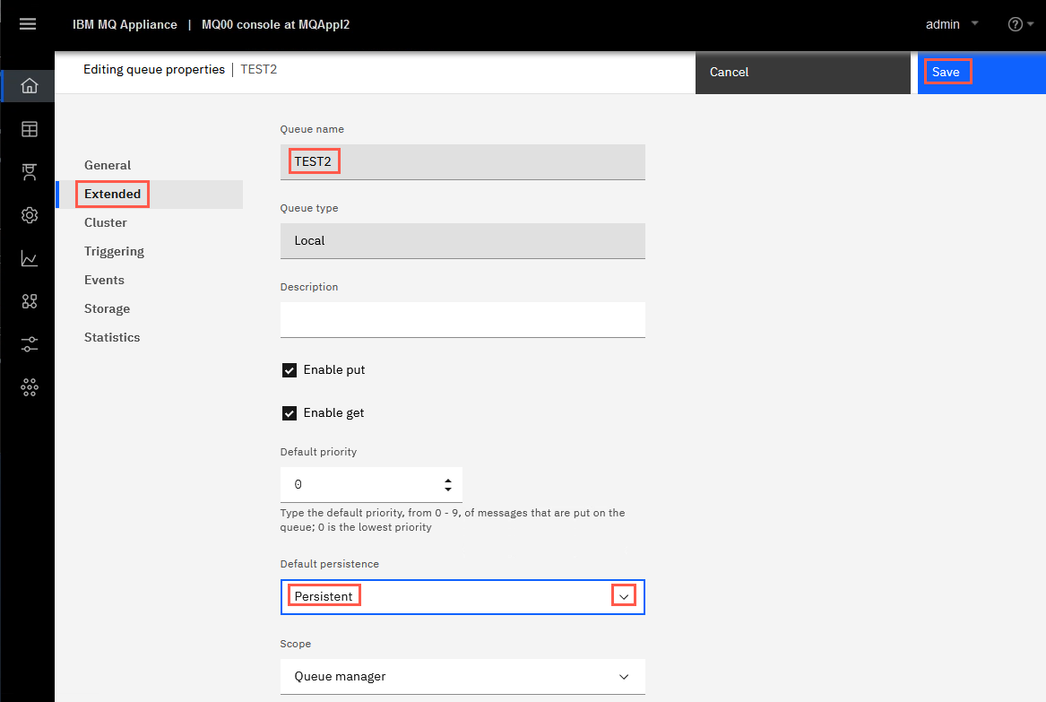
Click Edit and change the TEST2 queue default persistence to be persistent.
Click Save to save the change.
-
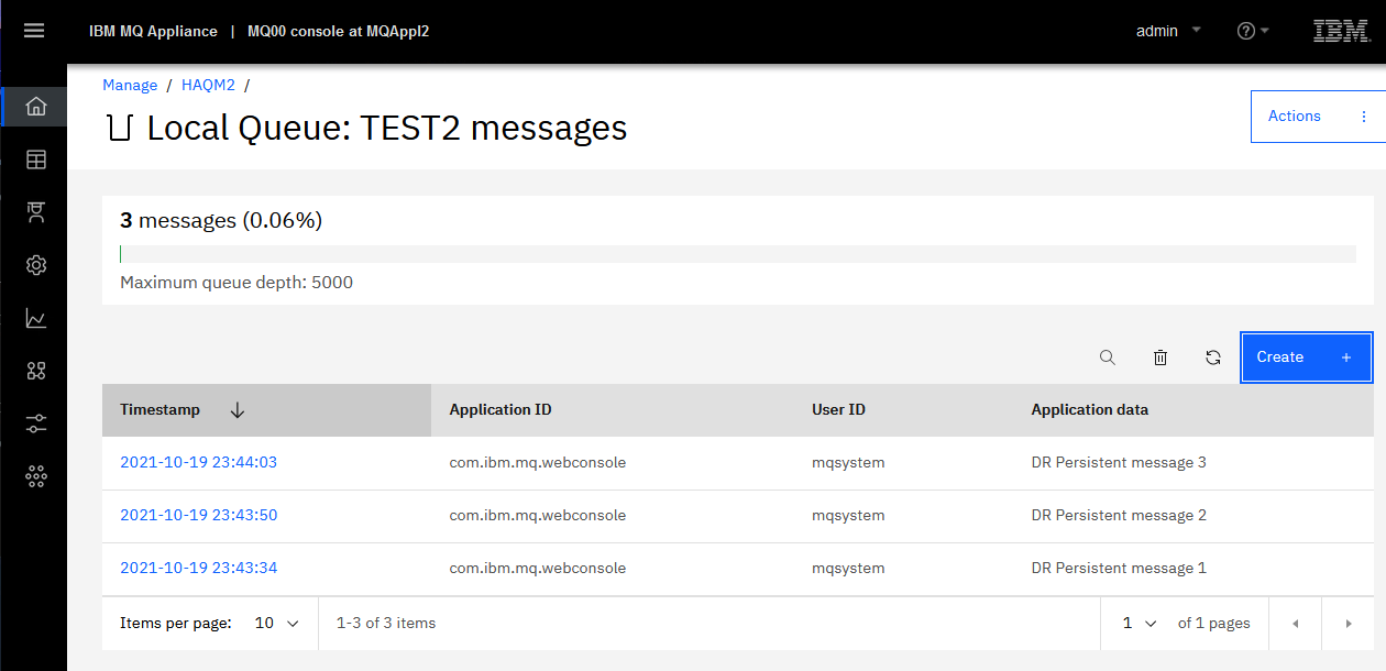
Click the hyperlink for TEST2, and put three messages on TEST2.
You are now ready to test DR.
Configure DR for HA queue manager
-
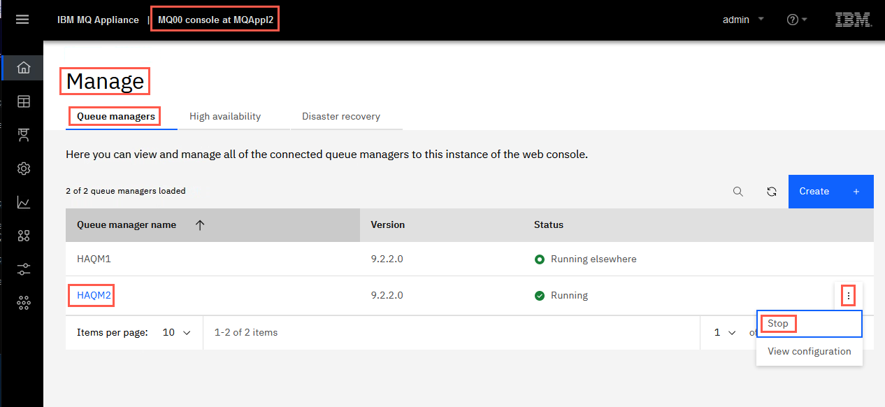
On the MQAppl1 MQ Console, navigate to Manage > Queue managers. Click the elipsis for HAQM1 then click Stop to end the queue manager HAQM1.
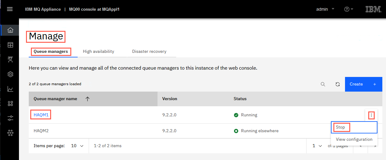
You will receive the green success pop-up.
-
Repeat the previous steps to stop HAQM2 on MQAppl2.
Create a DR primary and backup QM on recovery device
The next task is to create a DR primary (MQAppl2) queue manager and a backup queue manager on the recovery site (MQAppl3). Note that the HA appliance pair MQAppl1 and MQAppl2 need to be running also.
-
Make sure that the HA queue managers are not in split-brain status.
On MQAppl2’s command line, enter the command:
status HAQM2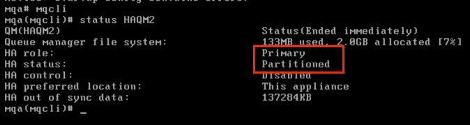
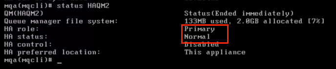
If the HA status shows Normal, skip to Partitioning Resolved - Continue.
In this instance, the HA status for HAQM2 shows Partitioned which is also called split-brain. The amount of data which is out of sync is shown to be 137284KB (what you see might differ slightly). This is easily resolved. Click this link to Resolve Partitioning. Then return here.
-
Check the status for HAQM2 again on MQAppl2’s command line. Status is now Normal.
Partitioning Resolved - Continue
-
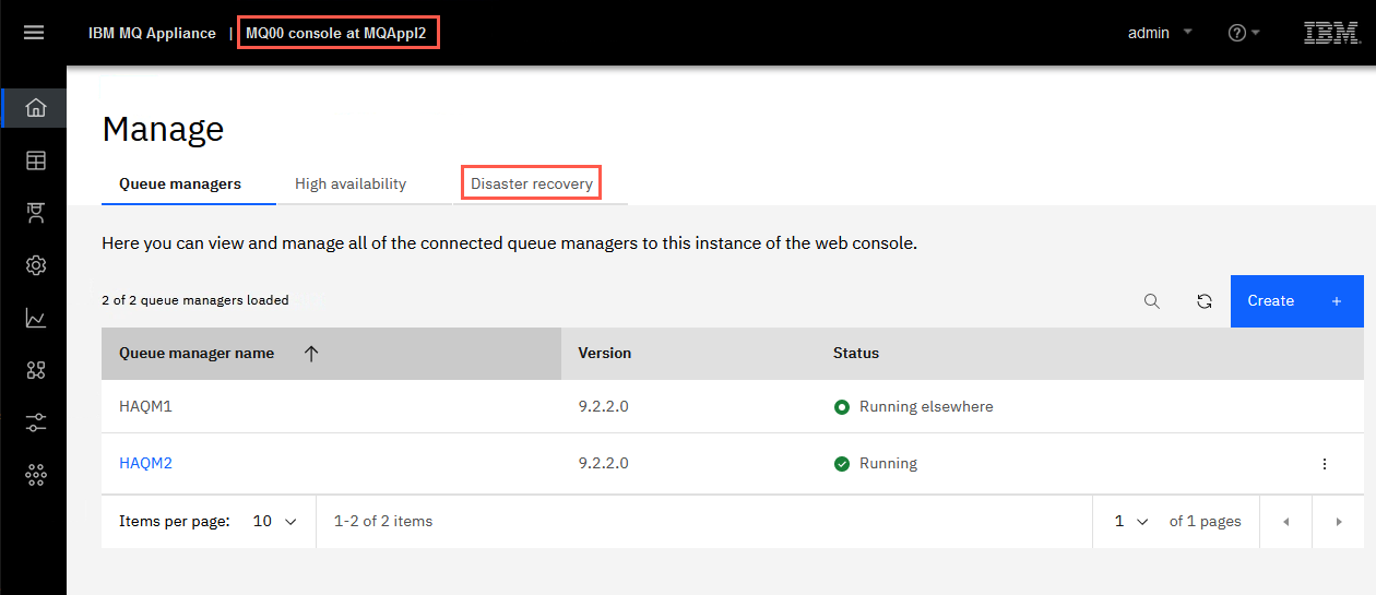
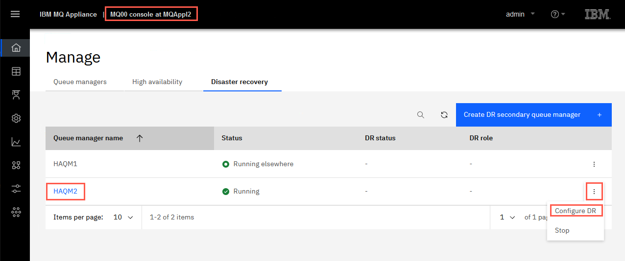
On the MQAppl2 browser session in Manage > Queue managers, click Disaster recovery.
-
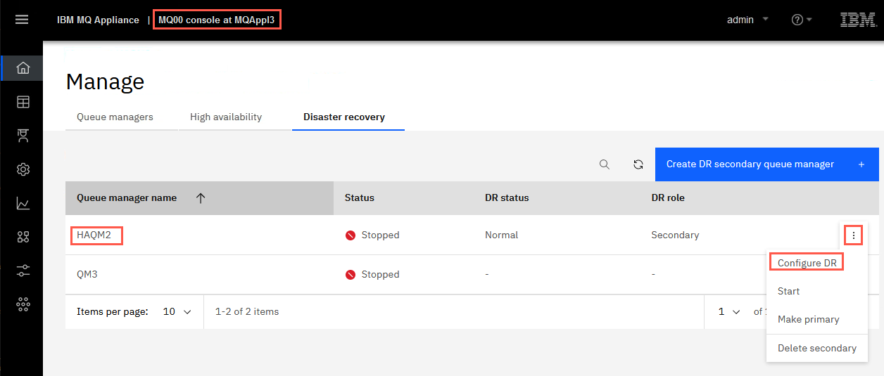
Click the elipsis for HAQM2 (stopped) and select Configure DR.
-
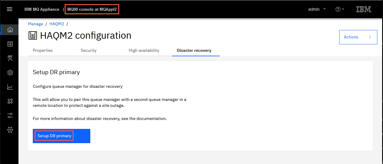
Click Setup DR Primary.
-
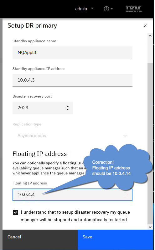
Specify that the HAQM2 queue manager is the primary instance in a disaster recovery configuration and include a floating IP address that can be used by either of the appliances in the HA pair.
Complete the dialog (below) with the IP address of eth4 from the DR site (MQAppl3) in the information as follows:
Standby appliance name: MQAppl3
Standby appliance IP address: 10.0.4.3 (or appropriate eth4 address of MQAppl3)
Disaster recovery port: 2023
Floating IP address: 10.0.4.14
Click Save.
If entering the command manually on the appliance CLI it would look like this:
crtdrprimary -m HAQM2 -r MQAppl3 -i 10.0.4.3 -p 2023 -f 10.0.4.14 -t -aThe parameters are as follows
-
-m queue manager name
-
-f Floating IP address of the high availability (HA) queue manager
-
-r name of the recovery appliance
-
-i ip address of DR replication interface on the recovery appliance
-
-p data replication listener port
-
-t replication type:
-
a asynchronous
The DR creation task can take a bit of time, wait at least a minute or two.
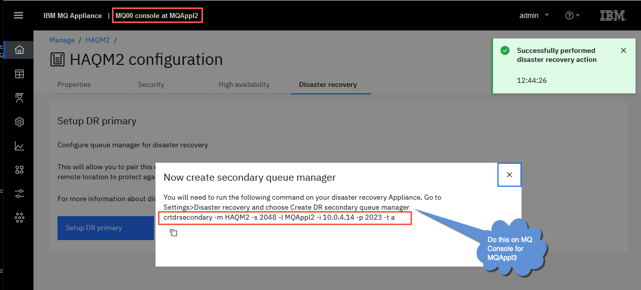
This generates the crtdrsecondary command which you need to run on MQAppl3. Copy the command in the pop-up window so that you can submit it on MQAppl3.
-
-
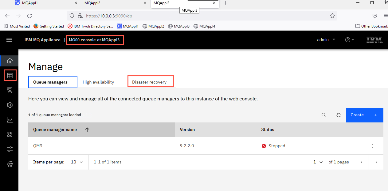
Logon to the MQAppl3 MQ Console via the browser. Navigate to Manage > Queue managers, then click Disaster recovery.
-
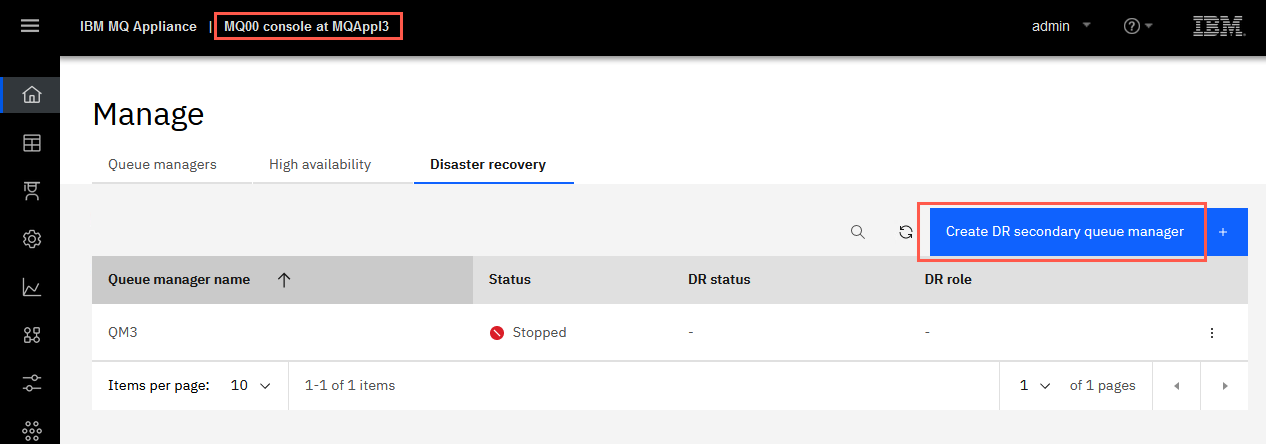
Click Create DR secondary queue manager button.
-
Paste the command you copied from MQAppl2 into the field where it says to “Enter command to setup secondary”. Notice the fields below are populated when you paste the command. You could also click the hyperlink and enter the fields manually if you didn’t copy from MQAppl2. But it is much easier to copy from MQAppl2 and paste on MQAppl3.
Click Create.
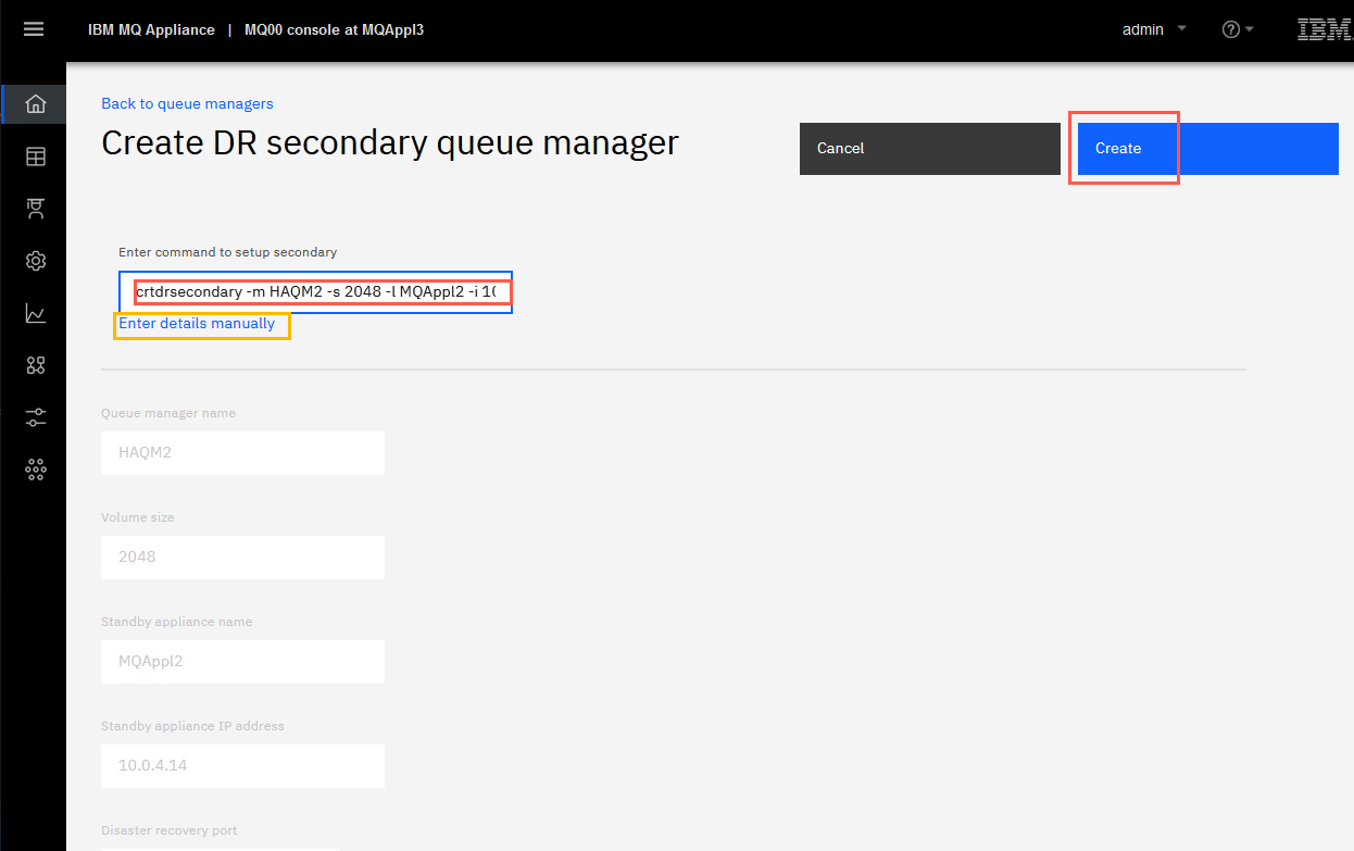
The command configures the queue manager on both appliances in the DR pair, and reserves storage for the data snapshot on both appliances. The command would look like this if entered manually on the appliance CLI:
crtdrsecondary -m HAQM2 -l MQAppl2 -i 10.0.4.14 -p 2023 -t -aThe parameters are as follows
-
-m queue manager name
-
-l name of the main appliance
-
-i ip address of DR replication interface on the main appliance
-
-p data replication listener port
-
-fs file system size in megabytes (MB)
-
-t replication type:
-
a asynchronous
The floating IP address is an IPv4 address that is used to replicate queue manager data from whichever HA appliance the queue manager is currently running on to the queue manager on the recovery appliance. The floating IP address must be in the same subnet group as the static IP address assigned to the replication port – eth4 (eth20 for physical appliances) – on both appliances. It also must be at least one greater than eth4’s address and unused.
Note that you do not physically configure an Ethernet port with this address. Select a free IP address in the same subnet as the replication ports on the two appliances, and specify it in the crtdrprimary command to make it the IP used for replication with the recovery appliance. You must specify a different floating IP address for each of the HA queue managers that you configure disaster recovery for.
-
-
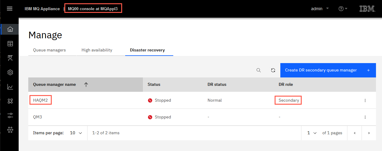
Wait for the command to complete (a few seconds) and you will see that HAQM2 is added to the Local Queue Managers. Note that its DR status is Secondary.
-
Return to the MQAppl2 browser and click Disaster recovery.
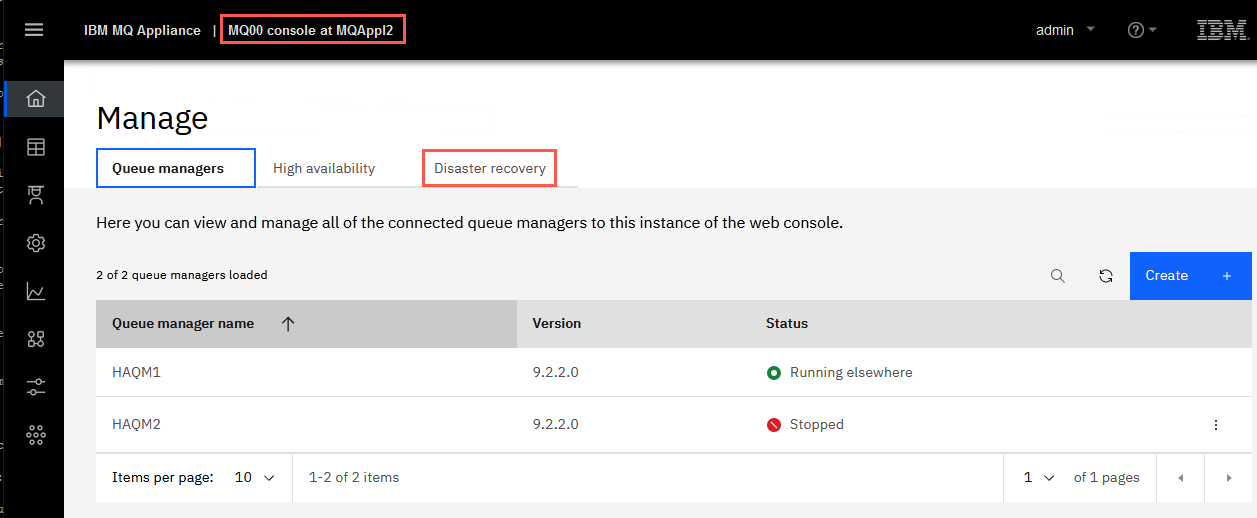
-
You will now see that HAQM2 has a DR status of Normal and DR role of Primary.
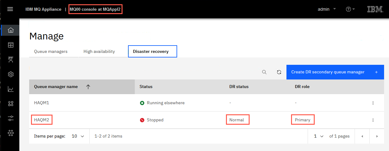
If the DR status for HAQM2 shows Normal ‘Synchronization in progress’, wait a few seconds for it to complete.
-
Click the elipsis for HAQM2 and select Configure DR to display the DR details.
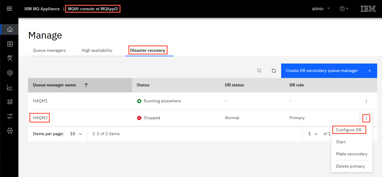
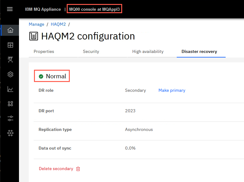
The display will reflect what you entered on the DR Create Primary command. It shows that the status is Normal and there is 0 data out-of-sync.
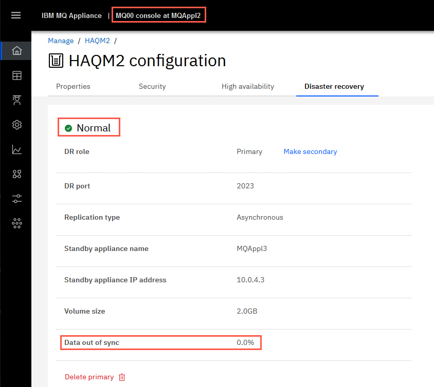
-
Repeat the DR Status command on MQAppl3’s MQ Console. Click the elipsis for HAQM2 and select Configure DR.
The status shows Normal on MQAppl3 also.
Test DR for HA group
You can simulate a disaster at the primary data center by shutting down the MQAppl1 and MQAppl2 virtual appliances.
-
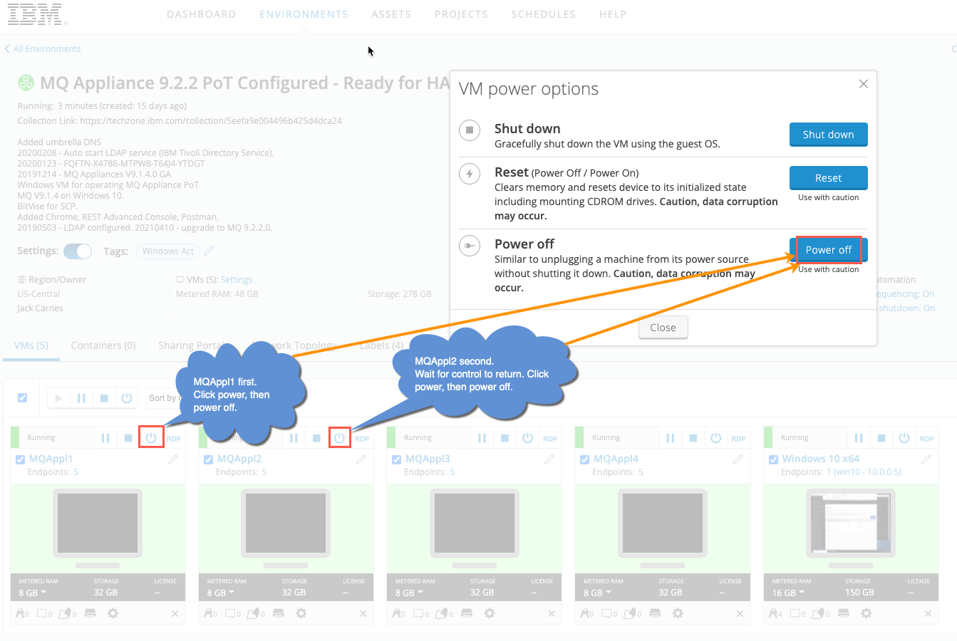
On the Skytap dashboard, shut down MQAppl1 first, then shutdown MQAppl2. You only need to wait between shutdowns as long as it takes Skytap to return control.
-
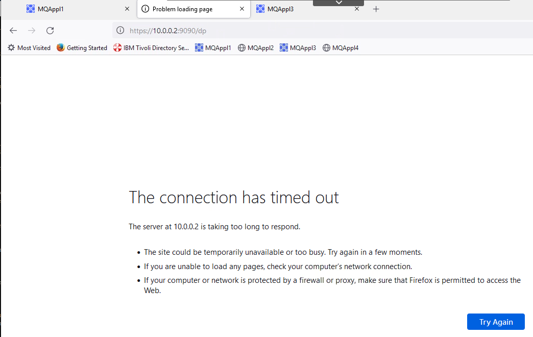
When MQAppl2 has been shut down, return to the MQAppl2 MQ Console. Wait for the “Lost communication with the server”, “Problem loading page”, or “The connection has timed out” message.
-
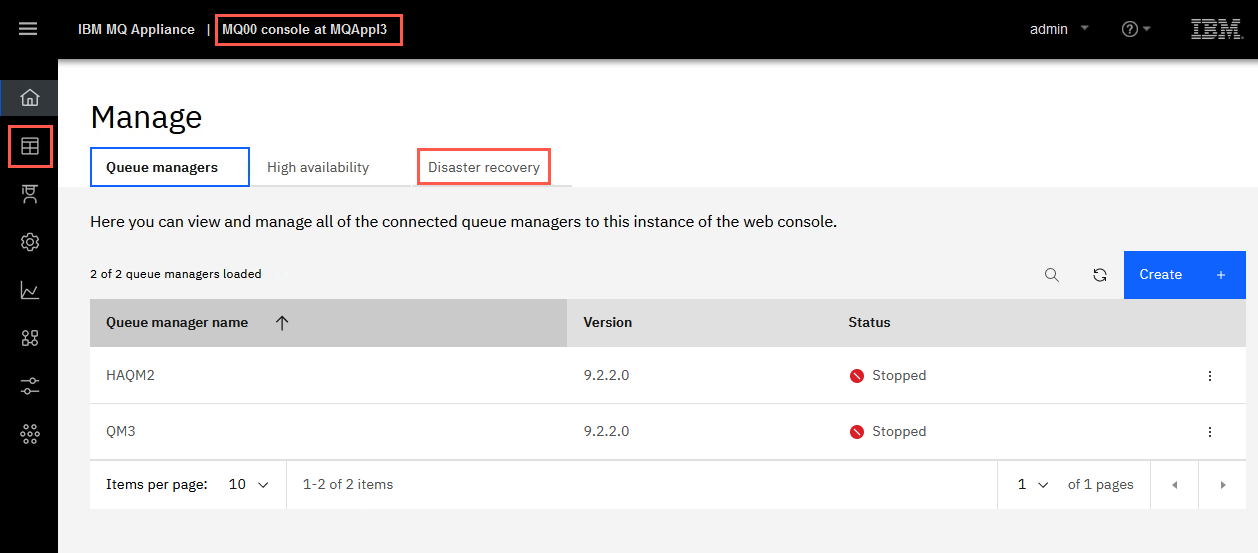
Now you can return to the MQAppl3 MQ Console. In Manage > Queue managers, click Disaster recovery.
-
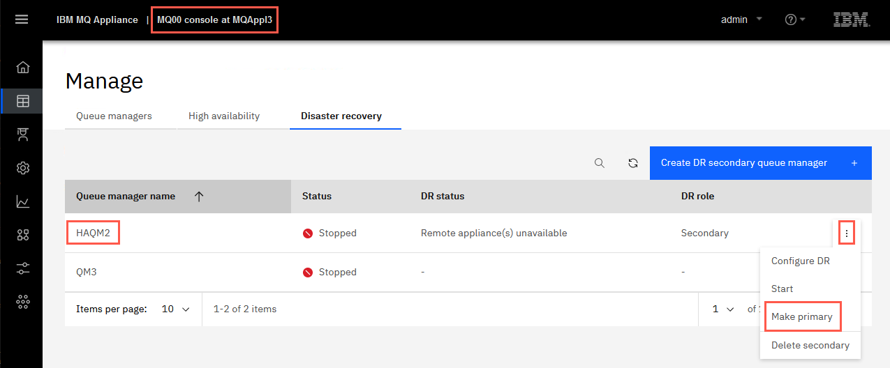
Click the elipsis for HAQM2 and select Make primary.
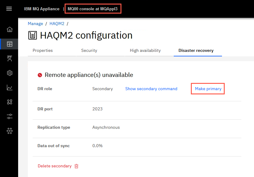
You could also select Configure DR, which takes you the status page where you can click the hyperlink for Make Primary.
-
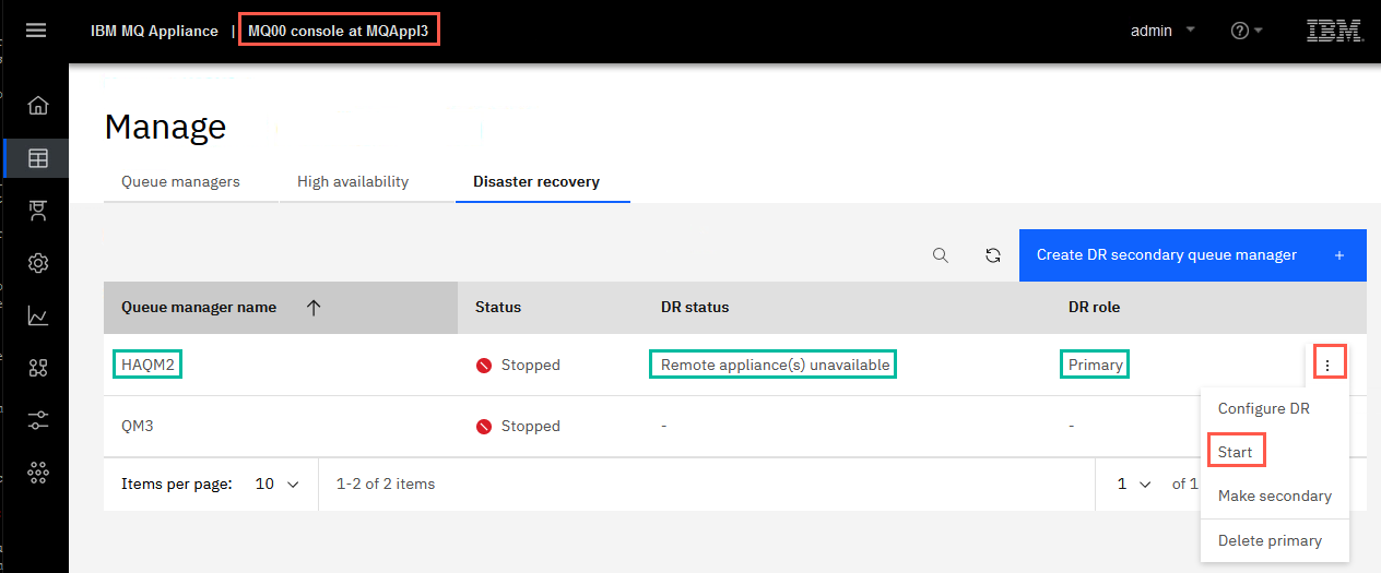
You will receive the green successful operation message. HAQM2 is now primary on MQAppl3 and can be started. Before you start the queue manager, check the DR status once more to see that it in fact shows DR primary. The status display shows that the remote appliance is no longer available and the recovery appliance is now the primary.
-
Now start the queue manager HAQM2 on the recovery appliance MQAppl3.
Once it is started, display its DR status:
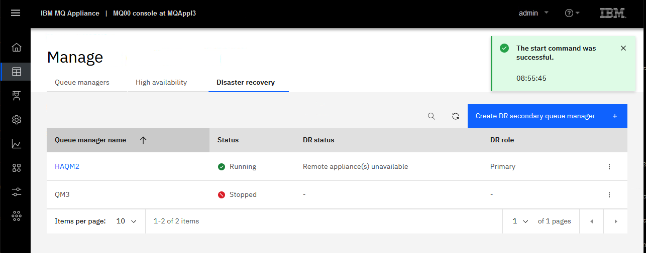
-
Click the elipsis for HAQM2 and select Configure DR. This will display the overall disaster recovery status for the queue manager.
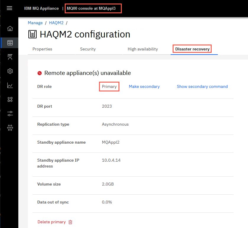
HAQM2 is now running and is now the DR Primary.
-
Click HAQM2 in the breadcrumbs.
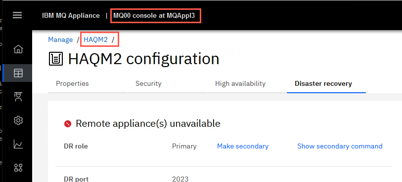
This will take you to the MQ Console for HAQM2 while it is now running on MQAppl3. By default Queues are displayed first.
-
Oh look! There are three messages on the TEST2 queue. This is expected since you gave TEST2 default persistence.
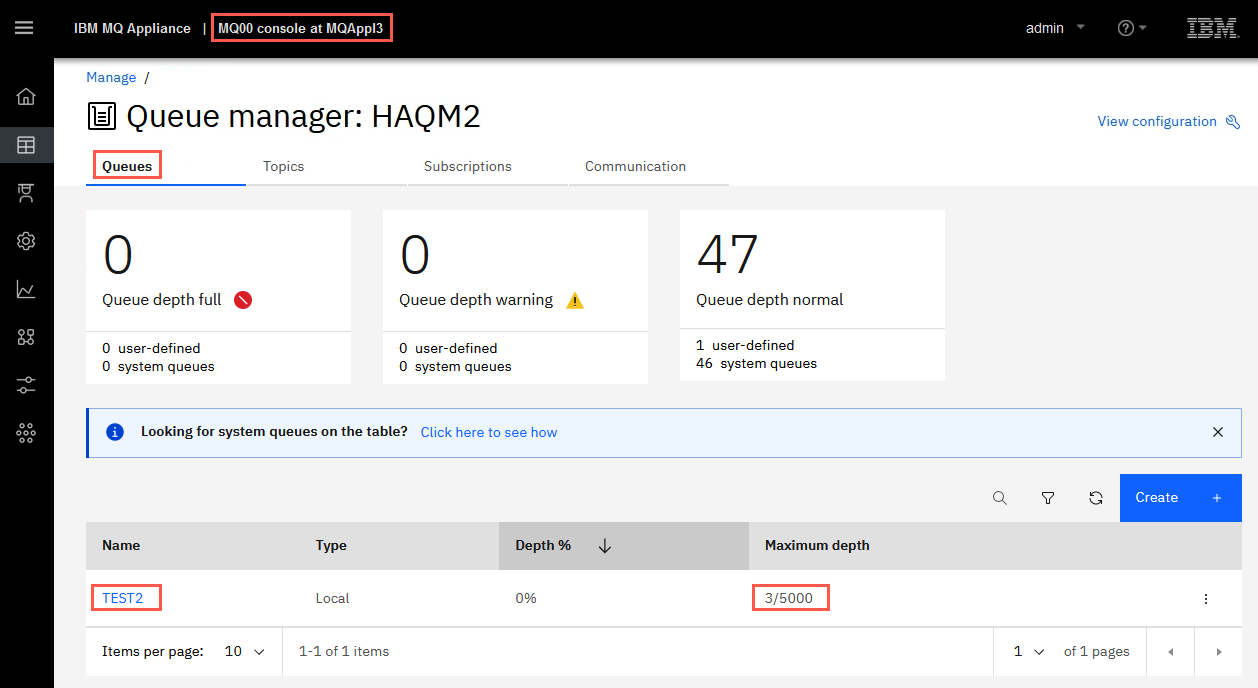
-
Browse those message by clicking the hyperlink for TEST2. As you would expect they are the messages you put on the queue while HAQM2 was running on MQAppl2.
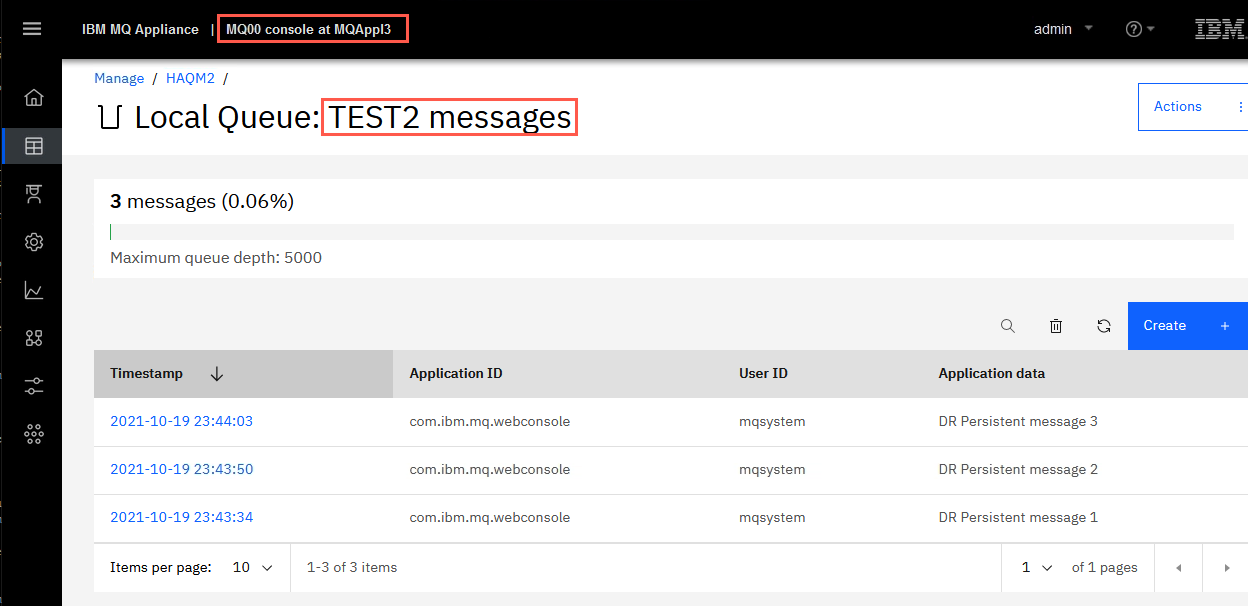
HAQM2 has successfully failed over to the disaster recovery site and all messages are available for processing. Client applications will need to reconnect to 10.0.0.3, and they would connect automatically if the CCDT has both addresses coded.
Congratulations, you have completed Lab 8 Disaster Recovery.
Resolve Partitioning
Resolving a partitioned problem in a high availability configuration
A partitioned problem occurs when the two appliances in a high availability configuration lose the ability to communicate with each other. If both the primary and secondary connections are lost, the queue manager will run on both appliances at the same time.
If the two appliances in your high availability configuration lose both primary and secondary interface connections, then replication no longer occurs between the two appliances. After the connection is restored, the data replication system detects that there have been independent changes to the same resources on both appliances. This situation is described as a partitioned situation, because the two appliances have two different views of the current state of the queue manager (it is sometimes called a ‘split-brain’ situation). When the first connection is restored (either primary or secondary), the queue manager is stopped on one appliance but continues to run on the other. The HA status is shown as partitioned.
Choosing the ‘winner’
To resolve the situation, you must decide which of the two appliances has the data that you want to retain, you then issue a command that identifies this appliance as the “”winner””. Data on the other appliance is discarded. The queue manager is then started on one appliance, and the data replicated to the other appliance.
To help you decide, you can run the status command for the affected queue manager on each appliance. The status command returns an HA status of partitioned together with a report of how much out-of-sync data the appliance has for that queue manager. See Viewing the status of a high availability queue manager.
You can also view the actual data associated with the affected queue manager on each appliance by interrogating the state of each queue manager. Stop all your HA queue managers and disable HA control by issuing the following command for each HA queue manager:
```
endmqm -w qmgr
```
Then follow these steps to run each affected queue manager on each appliance, outside of HA control, so that you can interrogate the state of each version of the queue manager:
-
Display the HA status to confirm that the HA control field shows disabled, and that the queue manager is ended on both appliances:
status qmgrSee Viewing the status of a high availability queue manager. (If the queue manager is running on the other appliance, end it there too.) You can use the HA last in sync field in the status reports to help determine when the queue manager data diverged and the seriousness of the partitioning.
-
On the appliance that is the primary for the queue manager, restart the queue manager outside of HA control:
strmqm -ns qmgrThis command starts the queue manager without starting the listener, to prevent any applications connecting. (If you need a listener in order to connect to the queue manager from, for example, IBM MQ Explorer, then you should start a listener manually by using a RUNMQSC command. Start the listener on a different port to the normal one so that applications cannot connect.)
-
Display the HA status again and verify that the queue manager is running and that HA control still shows disabled:
status qmgr -
Interrogate the state of the queue manager, for example, by browsing messages.
-
End the queue manager once more:
endmqm -w qmgr -
Display the HA status again and verify that the queue manager is ended on both appliances:
status qmgr -
Suspend the HA group on this appliance by entering the following command:
sethagrp -s -
Display the HA status of this appliance to confirm that it is in the standby state:
dsphagrp -
Log in to the other appliance and start the queue manager:
strmqm -ns qmgr(This command starts the queue manager without the listener. If you need a listener, see the advice in step 2.)
-
Check the status and confirm that the queue manager is running and that HA control is still disabled:
status qmgr -
Interrogate the state of the queue manager on that appliance, for example, by browsing messages.
-
End the queue manager:
endmqm -w qmgr -
Display the HA status and confirm that HA control is still disabled and that the queue manager is ended on both appliances.
-
Resume the suspended appliance:
sethagrp -r -
Display the HA status and confirm the suspended appliance is now active, and HA control is still disabled, and HA status is Partitioned on both appliances.
 dsphagrp
 status qmgr
Implementing your choice of winning appliance
It is a good idea to take back ups of both sets of data before you implement your choice of ‘winner’, see Backing up a queue manager.
You identify the winner by running the following commands on the chosen appliance:
-
Make the queue manager on the winning appliance the primary:
makehaprimary HAQMName -
Where HAQMName is the name of the queue manager. The data is then synchronized between the queue managers on the winning appliance and the other appliance. Check the HA status to confirm that synchronization has finished and a status of Normal is reported on both appliances:
status qmgr -
Start the queue manager with HA control:
strmqm qmgr -
Whichever appliance that you start the queue manager on, it should run on the appliance that has been designated as its preferred appliance. Display the HA status on both appliances and confirm HA control is enabled and the queue manager is active on only the preferred appliance:
status qmgr
Other situations
If the two appliances lose the replication interface, the HA status is reported as Remote appliance(s) unavailable. The running queue manager might accumulate out-of-sync data. The other queue manager remains in standby with no out-of-sync data. When the connection is remade, replication is resumed.
If your HA queue manager is configured for disaster recovery, and failed over to the recovery appliance when your HA group went out of service, then you might have to resolve data partitioning between the HA group and the recovery appliance. After you have restored your HA group, and resolved data partitioning between the primary and secondary appliances, you must follow the procedure described in Switching back to the main appliance.